Projection optical system, exposure apparatus, and method of manufacturing device

Inactive Publication Date: 2009-03-26
CANON KK
View PDF5 Cites 36 Cited by
  • Summary
  • Abstract
  • Description
  • Claims
  • Application Information

AI Technical Summary

Benefits of technology

[0015]It is an exemplary object of the present invention to provide a projection optical system which achieves good opti

Problems solved by technology

An increase in the aperture of a glass material with an increase in NA has become a large factor that increases the cost of an exposure apparatus.
This causes a large difference in pupil shape between on-axis light and off-axis light, resulting in an increase in so-called pupil aberration.
As pupil aberrations, especially the curvature of field of the pupil and the comatic aberration of the pupil increase, the image-side telecentric characteristic of a projection optical system deteriorates,

Method used


Image

  • Projection optical system, exposure apparatus, and method of manufacturing device
  • Projection optical system, exposure apparatus, and method of manufacturing device
  • Projection optical system, exposure apparatus, and method of manufacturing device

Examples


first numerical embodiment

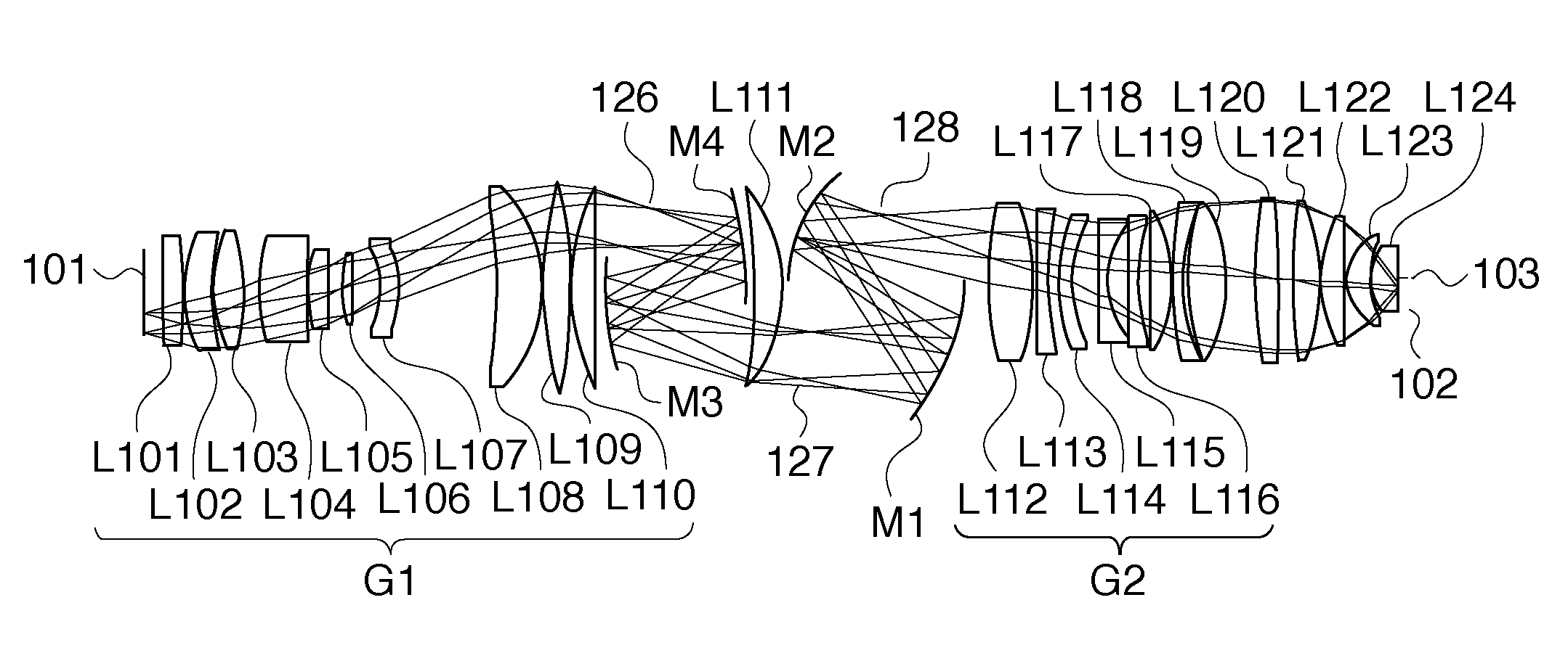
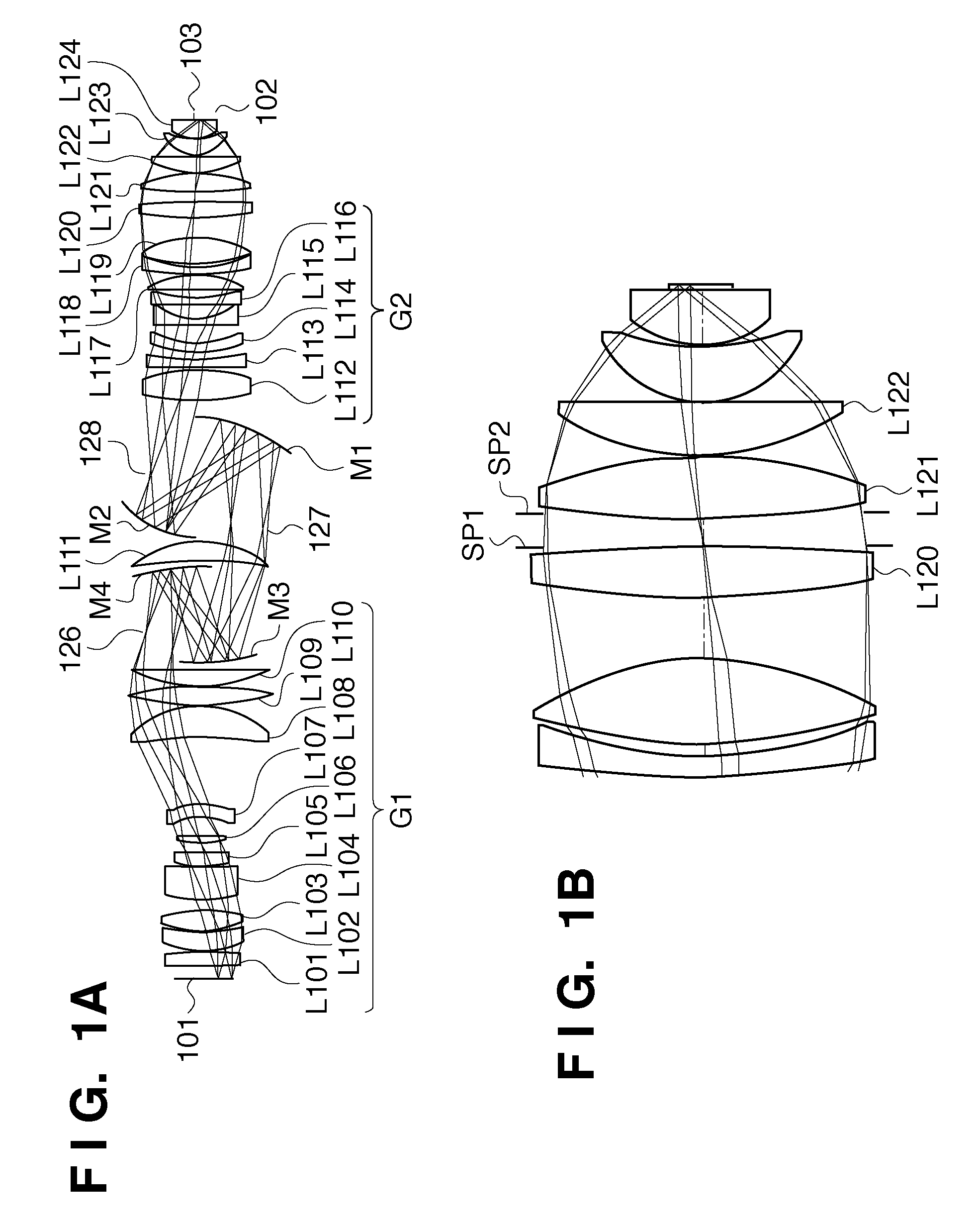
[0060]FIG. 1A shows the lens arrangement of a catadioptric projection optical system as the first numerical embodiment. Referring to FIG. 1A, the imaging optical system G1, the intermediate image 127 of the real image, the reflecting concave mirror M1, the concave mirror M2, the intermediate image 128 of the real image, and the imaging optical system G2 are sequentially arranged from the first object 101 side along the optical path.

[0061]In the first numerical embodiment, the imaging optical system G1 comprises lenses L101 to L110, a concave mirror M3, a concave mirror M4, and a lens L111. More specifically, the imaging optical system G1 sequentially has, from the first object side, the aspherical positive lens L101 having a nearly plano-convex shape with its nearly flat surface facing the first object side, the aspherical positive lens L102 having a meniscus shape with its convex surface facing the first object side, and the positive lens L103 having a biconvex shape. Following the...

second numerical embodiment

[0074]Tables 4 and 5 show various constituent factors or elements of the second numerical embodiment.

TABLE 4NA = 1.20β = ¼Radius of CurvatureSurface Interval[mm][mm]Materialr0 = ∞d0 = 25.19881r1 = 10146.97189d1 = 33.27555SiO2Asphericalr2 = −696.78276d2 = 1.59058Surfacer3 = 223.04724d3 = 41.44895SiO2Asphericalr4 = 621.07430d4 = 2.39338Surfacer5 = 223.44378d5 = 46.39318SiO2r6 = −310.19954d6 = 20.93568r7 = 281.76963d7 = 70.00000SiO2r8 = 478.35430d8 = 1.05014r9 = 156.81626d9 = 32.00000SiO2Asphericalr10 = 1393.77884d10 = 21.26122Surfacer11 = 192.11219d11 = 18.04448SiO2r12 = −438.32491d12 = 39.17674r13 = −138.24946d13 = 29.94391SiO2Asphericalr14 = −140.10195d14 = 142.39793Surfacer15 = −938.67110d15 = 69.95628SiO2r16 = −222.66871d16 = 3.02453Asphericalr17 = 463.33151d17 = 40.03651SiO2Surfacer18 = −777.63117d18 = 1.01162r19 = 362.03914d19 = 37.24490SiO2r20 = −37671.40243d20 = 222.43920Asphericalr21 = −453.83756d21 = −209.43920M1SurfaceAsphericalr22 = 476.77816d22 = 219.45691M2Surfacer23 = −...

third numerical embodiment

[0082]FIG. 8A shows the lens arrangement of a dioptric projection optical system as the third numerical embodiment of the present invention. The dioptric projection optical system comprises an imaging optical system G1 and an imaging optical system G2 sequentially arranged from the first object 101 side along an optical path.

[0083]In the third numerical embodiment, the imaging optical system G1 comprises lenses L301 to L316. More specifically, the imaging optical system G1 sequentially has, from the first object side, the aspherical negative lens L301 having a biconcave shape with its concave surface facing the first object side, the negative lens L302 having a meniscus shape with its concave surface facing the first object side, and the aspherical positive lens L303 having a meniscus shape with its concave surface facing the first object side. Following the lens L303, the imaging optical system G1 sequentially has the positive lens L304 having a biconvex shape, the positive lens L3...


PUM


Abstract

A projection optical system which projects an image of a first object onto a second object includes a plurality of lenses and a plurality of aperture stops for determining a numerical aperture. The plurality of aperture stops include a first aperture stop having an opening whose size can be changed, and a second aperture stop having an opening whose size can be changed. The first and second aperture stops are positioned nearer to the second object than a lens having the maximum effective diameter among the lenses included in an imaging optical system nearest to the second object. At least one of the first and second aperture stops is positioned at or near the pupil of the imaging optical system. The range of the numerical aperture determined by the first aperture stop is larger than the range of the numerical aperture determined by the second aperture stop.

Description

BACKGROUND OF THE INVENTION[0001]1. Field of the Invention[0002]The present invention relates to a projection optical system, an exposure apparatus, and a method of manufacturing a device.[0003]2. Description of the Related Art[0004]Conventionally, a projection exposure apparatus has been widely used, which projects a circuit pattern drawn on a reticle onto a wafer or the like as a substrate by using a projection optical system and transfers the circuit pattern onto the wafer.[0005]Recently, with demands for miniaturization of semiconductor devices, higher resolutions have been required for projection optical systems. In order to meet this requirement, the wavelength of exposure light may be decreased, and the numerical aperture (NA) of a projection optical system may be increased. An immersion projection optical system has also been proposed, which can achieve an NA of 1 or more by a so-called immersion technique of filling the space between the final lens (final surface) of a proj...

Claims


Application Information

Patent Timeline
IPC IPC(8): G02B27/18G03B27/32
CPCG02B13/22G02B17/0848G02B17/0892G03F7/70275G03F7/70225G03F7/7025G03B27/32
Inventor OZAWA, KAZUYOSHI
Owner CANON KK
Why Eureka
Try Eureka