Audio characteristic correction system

Active Publication Date: 2007-02-15
YAMAHA CORP
View PDF14 Cites 38 Cited by
  • Summary
  • Abstract
  • Description
  • Claims
  • Application Information

AI Technical Summary

Benefits of technology

[0010] In accordance with this invention, which has a measurement means for measuring audio characteristics of sounds reflected on the wall surface or sound reflection board and a control means for controlling at least one of frequencies, gain characteristics, frequency-phase characteristics, and gains of the characteristic correction means based on measurement results in such a way that sounds reflected on the wall surface or sound reflection board have desired audio characteristics at a listen

Problems solved by technology

However, this audio digital surround system, in which plural speakers are spread out and distributed in the listening room Zone, suffers from various drawbacks in that in order to arrange the rear speakers SP-SL and SP-SR for surround playback in the rear of the listening position U, wiring lengths therebetween must be increased, and in that the arrangement of the rea

Method used


Image

  • Audio characteristic correction system
  • Audio characteristic correction system
  • Audio characteristic correction system

Examples


Example

First Embodiment

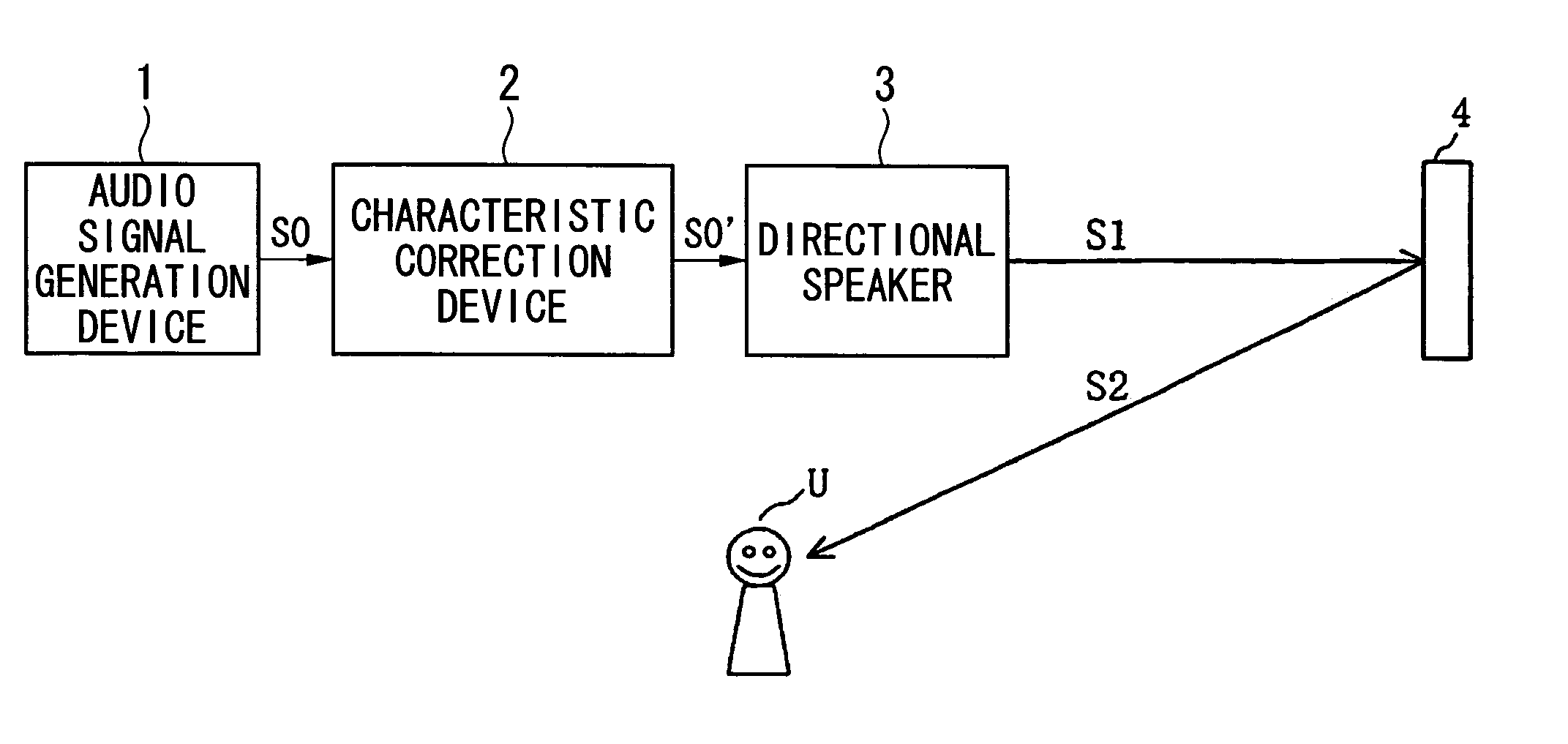
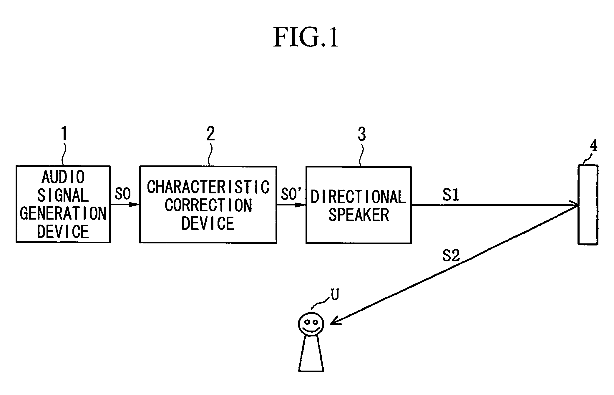
[0031]FIG. 1 is a block diagram showing the constitution of an audio characteristic correction system in accordance with a first embodiment of this invention. The audio characteristic correction system is applied to an audio surround system, wherein FIG. 1 shows only the constitution for a surround channel (i.e., a rear left signal SL or a rear right signal SR), and it does not show the constitution for a main channel (i.e., a main left signal L or a main right signal R).

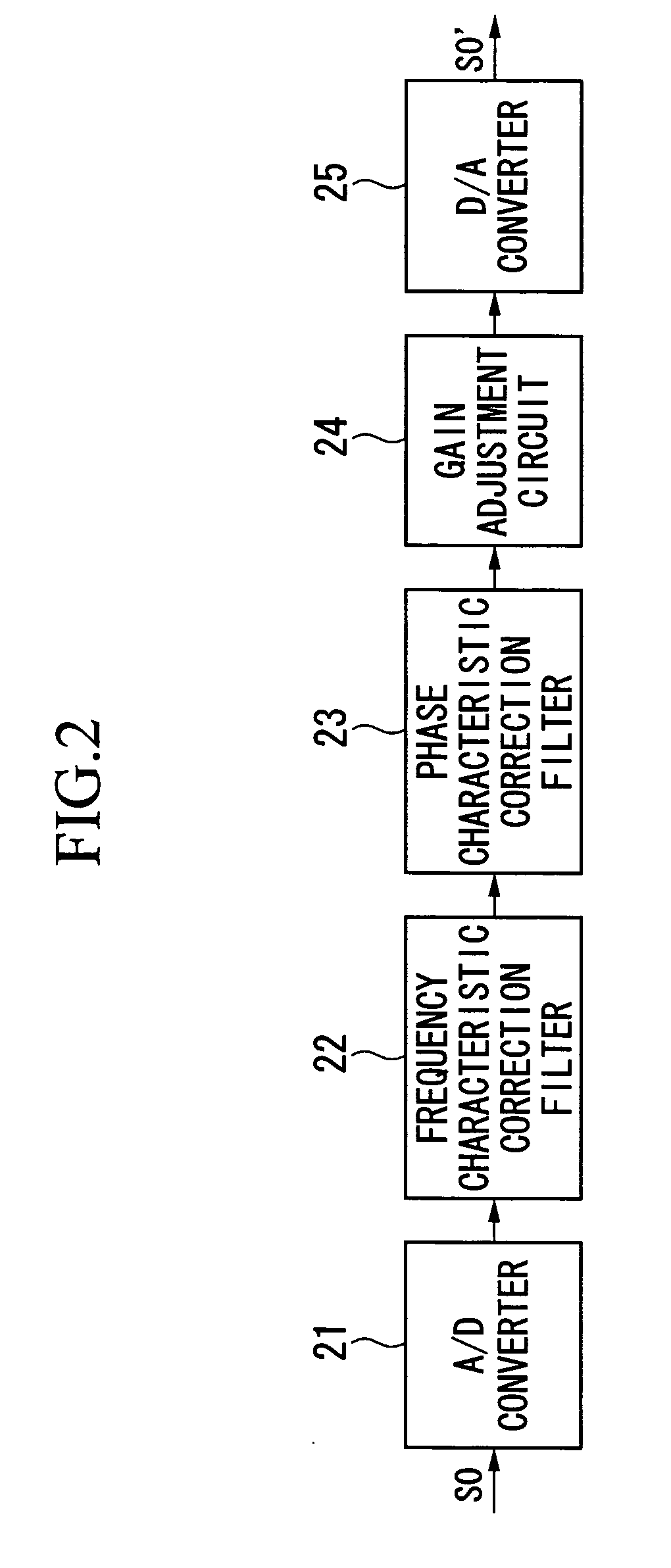
[0032] The audio characteristic correction system in accordance with the first embodiment is constituted by an audio signal generation device 1 such as a DVD / CD player and an AV amplifier (audio-visual amplifier), a characteristic correction device 2 for correcting at least one of frequency-gain characteristics (or frequency-amplitude characteristics), frequency-phase characteristics (or group delay characteristics), and gains of audio signals output from the audio signal generation device such tha...

Example

Second Embodiment

[0046] Next, a second embodiment of this invention will be described. The second embodiment uses an array speaker as the directional speaker 3 shown in the first embodiment.

[0047]FIG. 4 is a block diagram showing an example of the constitution of the directional speaker 3 using an array speaker. The directional speaker 3 in the second embodiment includes a delay circuit 31 for applying a delay time, corresponding to directivities (focal positions of sounds) to be realized, to an audio signal SO′ output from the characteristic correction device 2, plural gain adjustment circuits 32 (32-1 to 32-n) for adjusting gains of output signals of the delay circuit 31 to prescribed levels, plural amplifiers 33 (33-1 to 33-n) for amplifying output signals of the gain adjustment circuits 32, and plural speakers 34 (34-1 to 34-n) driven by the amplifiers 33.

[0048] The directional speaker 3 controls directivities of sounds emitted from the speakers 34 such that the sounds are di...

Example

Third Embodiment

[0054] Next, a third embodiment of this invention will be described. FIG. 8 is a block diagram showing an audio characteristic correction system in accordance with the third embodiment, wherein parts identical to those of the first embodiment shown in FIG. 1 are designated by the same reference numerals. The audio characteristic correction system of the third embodiment includes an audio signal generation circuit 1, a characteristic correction device 2, a directional speaker 3, a microphone 5, a characteristic analysis device 6 for analyzing audio characteristics of sounds picked up by the microphone 5, a characteristic correction control device 7 for controlling at least one of frequency-gain characteristics, frequency-phase characteristics, and gain of the characteristic correction device 2 based on the analysis results of the characteristic analysis device 6 such that a sound S2 reflected on the wall surface or the sound reflection board 4 has desired audio chara...


PUM


Abstract

An audio characteristic correction system adapted to an audio surround system in which a sound emitted from a directional speaker (an array speaker) is reflected on a wall surface or a sound reflection board so as to create a virtual speaker, at least one of frequency-gain characteristics, frequency-phase characteristics, and gain of an audio signal input to the directional speaker is corrected such that the sound reflected on the wall surface or the sound reflection board has desired audio characteristics at a desired listening position.

Description

TECHNICAL FIELD [0001] This invention relates to audio characteristic correction systems and in particular to audio surround systems, in which sounds (or sound beams) emitted from directional speakers such as array speakers are reflected on wall surfaces of desired rooms or on sound reflection boards so as to create virtual sound sources, wherein audio characteristic correction systems correct audio characteristics of sounds reflected on sound reflection boards. BACKGROUND ART [0002] Recently, various types of audio sources have been distributed and provided in open markets; hence, 5.1-channel multi-channel audio signals are recorded on DVDs (digital versatile disks), for example. Audio digital surround systems for reproducing audio sources have become common in households. FIG. 11 is a plan view showing an example of arrangement of speakers in an audio digital surround system, wherein reference symbol Zone designates a listening room for use in audio surround playback; reference sy...

Claims


Application Information

Patent Timeline
IPC IPC(8): H03G3/00H04R3/12H04R1/34H04S3/00H04S7/00
CPCH04R3/12H04S7/307H04S3/00H04R2203/12H04S7/301
Inventor KONAGAI, YUSUKEUSUI, AKIRA
Owner YAMAHA CORP
Why Eureka
Try Eureka