Method of implementing multi-transfer curve phase lock loop

a phase lock loop and transfer curve technology, applied in the field of electronic circuits, can solve the problem of adding to the cost of manufacturing the plls

Inactive Publication Date: 2006-01-12
FARADAY TECH CORP
View PDF2 Cites 43 Cited by
  • Summary
  • Abstract
  • Description
  • Claims
  • Application Information

AI Technical Summary

Problems solved by technology

This factory testing and hard-wiring of the CCO adds to the cost of manufacturing the PLLs.

Method used


Image

  • Method of implementing multi-transfer curve phase lock loop
  • Method of implementing multi-transfer curve phase lock loop
  • Method of implementing multi-transfer curve phase lock loop

Examples


Embodiment Construction

[0020] A detailed description of an embodiment of the present invention is provided in the following.

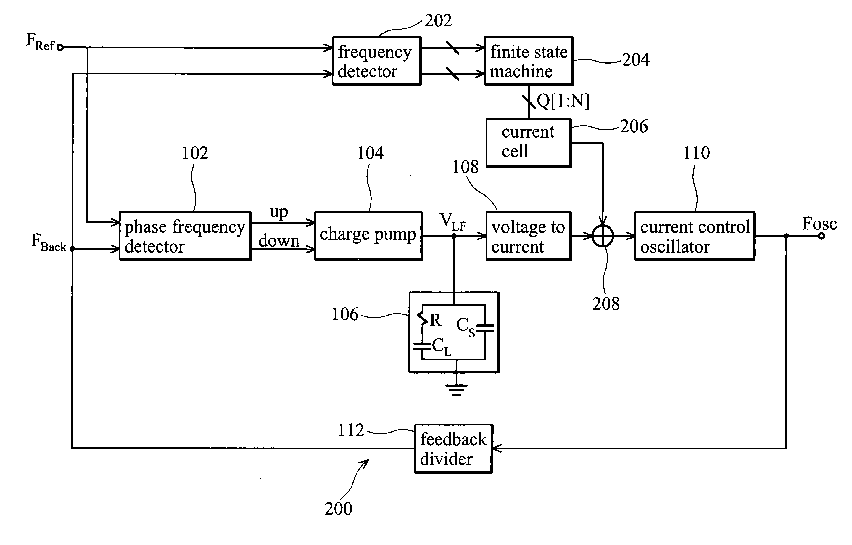
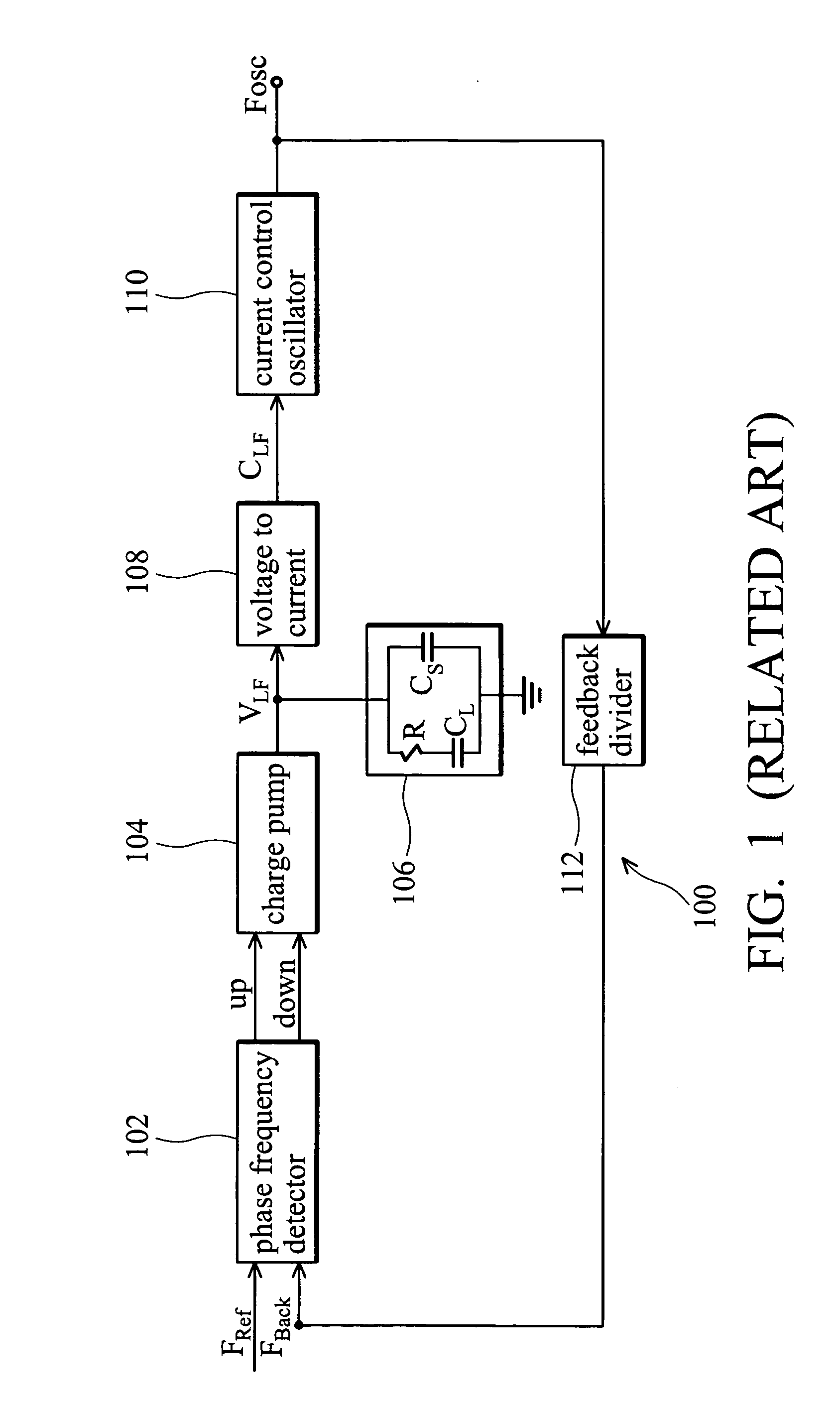
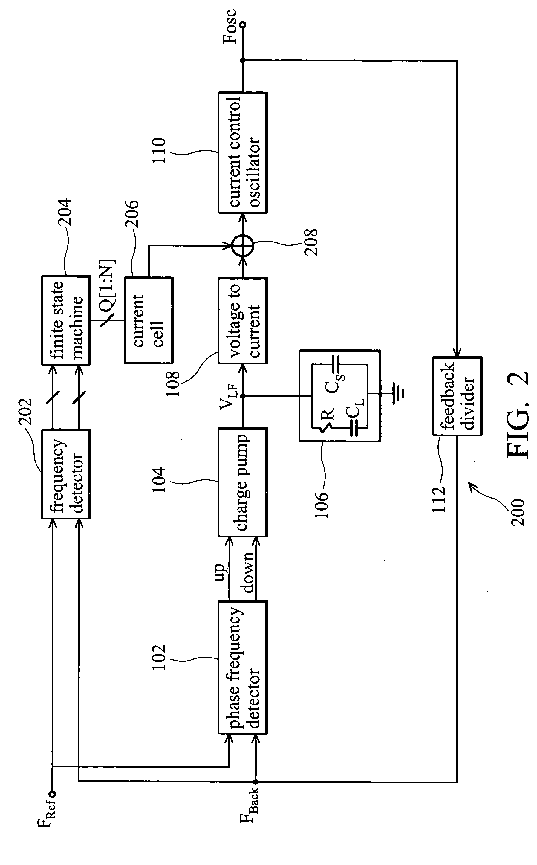
[0021]FIG. 2 shows a block diagram of a charge bump-based phase-lock loop 200, according to one embodiment of the present invention. In PLL 200, phase frequency detector (PFD) 102, charge pump 104, loop filter 106, voltage to current (V2C) 108, current control oscillator (CCO) 110 and feedback divider 112 are analogous to the corresponding components of PLL 100 of FIG. 1. In addition, PLL 200 comprises frequency detector 202, state machine 204, current cell 206 and current adder 208. These components are designed to enable PLL 200 to automatically select an appropriate operating curve whenever the PLL 200 is powered on.

[0022] In FIG. 2, the frequency detector 202 detects the frequency difference of the reference signal FRef and the feedback signal FBack, and the state machine 204 determines whether a condition state is appropriate. The state machine delivers digital values N (the v...


PUM


Abstract

A phase-lock loop (PLL) has an oscillator comprising a plurality of operating curves. A method for implementing a multi-transfer curve in a phase lock loop. By means of a finite state machine cooperating with a current cell, the unwanted loop gain is effectively reduced to produce a wide-ranging operating curve.

Description

BACKGROUND OF THE INVENTION [0001] The present invention relates to electronic circuits, and in particular, to phase-lock loops. [0002] In modern technologies, signals having gigahertz frequency, requiring phase-lock loops are the foundation for various applications. A phase-lock loop (PLL) is a circuit that generates a periodic output signal having a constant phase relationship with respect to a periodic input signal. [0003]FIG. 1 shows a block diagram of a conventional charge pump-based phase-lock loop 100. Phase / frequency detector (PFD) 102 compares the phase θRef of the input signal FRef to the phase θback of the feedback signal Fback and generates an error signal, either an up signal (when θRef leads θback) or a down signal (when θback leads θRef), where the width of the error signal pulse indicates the magnitude of the difference between θRef and θBack. [0004] Charge pump 104 generates an amount of charge equivalent to the error signal (either up or down) from PFD 102. Dependi...

Claims


Application Information

Patent Timeline
Patent Type & Authority Applications(United States)
IPC IPC(8): H03L7/06
CPCH03L7/0896H03L7/18H03L7/113
Inventor FAN-JIANG, CHAO-HSIN
Owner FARADAY TECH CORP
Why Eureka
Try Eureka