
Imaging device

a technology of image pickup and hood, which is applied in the direction of camera filters, television systems, instruments, etc., can solve the problems of image pickup, image pickup, flare generation, etc., and achieve the effect of laborious operation of detaching the lens hood

Inactive Publication Date: 2006-01-12
SONY CORP
View PDF13 Cites 43 Cited by
  • Summary
  • Abstract
  • Description
  • Claims
  • Application Information

AI Technical Summary

Benefits of technology

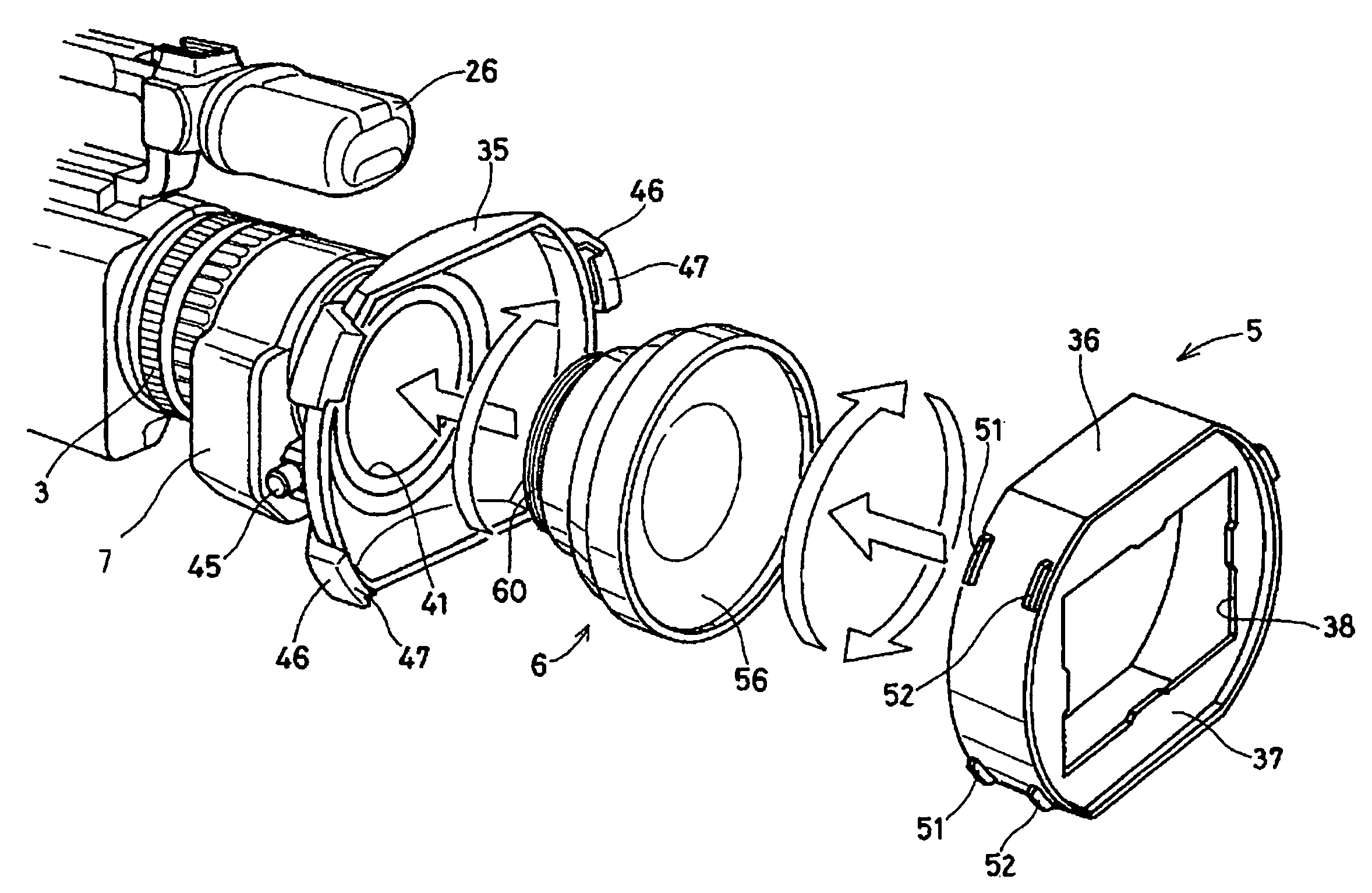
[0014] Here, it is preferable that a dowser is provided in the inside of the tubular portion of the lens hood, and the incident light is contracted by an opening of the dowser. In addition, it is preferable that the tubular portion and the base portion of the lens hood are detachably coupled to each other by a bayonet claw. Besides, it is preferable that a cap is detachably attached to the opening in the dowser of the tubular portion of the lens hood. In addition, the another lens is preferably a wide conversion lens for widening the image pickup angle.
[0016] In a conventional image pickup apparatus, the light-shielding function has been given priority so that it has been necessary to detach a lens hood and use a conversion lens in the case of using the conversion lens when the lens hood is used. Therefore, the lens hood effect has naturally not been expectable, and the operation of detaching the lens hood has been laborious. In view of this, in a preferred embodiment of the present invention, a part of the lens hood is structured to be attachable and detachable, and the conversion lens can be used in the condition where the lens hood of the camera is left mounted, so that, by mounting the part of the hood while reversing it between the attached state and the detached state, the light-shielding effect can be displayed irrespectively of whether the conversion lens is mounted or is not mounted.
[0017] According to such an embodiment, even in the case of using the conversion lens, the conversion lens can be contained into the lens hood so as to be used, by only detaching and attaching a part of the lens hood without removing the hood. In addition, by mounting the detachably attached part through reversion, the light-shielding effect can also be obtained. Besides, even in the case of not using the conversion lens, the light-shielding effect of the ordinary lens hood can be obtained by reversing the detached portion to the initial condition and attaching it in the initial condition.
[0019] Therefore, according to such an image pickup apparatus, the another lens is contained in the inside of the base portion of the lens hood, so that it suffices, in the case of mounting the another lens, to mount the another lens in the condition where the base portion of the lens hood is mounted, and thereafter to couple the tubular portion of the lens hood to the base portion. Accordingly, the light-shielding effect of the lens hood can be expected even in the case of using the another lens, and the laborious operation of detaching the hood is not needed in the case of mounting the another lens.
[0022] The present invention provides in an embodiment an image pickup apparatus so configured that, even in the case of using an auxiliary optical system, the contracting of the incident light by a dowser of a lens food can be achieved, thereby preventing the generation of flare on an image pickup screen.

Problems solved by technology

When a point light source is put in an object at the time of shooting by a video camera, non-imaging light reflected by an air-glass joint plane of a shooting lens or the like reaches the image pickup screen to form irregular light spots, leading to the generation of flare and to a trouble in image pickup.
When a short lens hood is thus mounted on the front side of the shooting lens at the time of shooting by a video camera, an image pickup screen with its corner portions not lost can be obtained, but the amount of light received by the shooting lens is so large that a point light source is easily put in to the object side, leading to the generation of flare on the image pickup screen.
Therefore, the flare preventive function by contracting the incident light with the dowser of the lens hood cannot be expected, and the operation of detaching the lens hood is laborious.
However, where the auxiliary optical system such as a conversion lens is used, the incident light is refracted by the conversion lens so largely that the incident light contracting effect of the hood frame body cannot be expected.

Method used


Image

  • Imaging device
  • Imaging device
  • Imaging device

Examples


Embodiment Construction

[0039] The present invention relates to an image pickup apparatus, particularly to an image pickup apparatus in which a lens hood is mounted on the front side of an optical system.

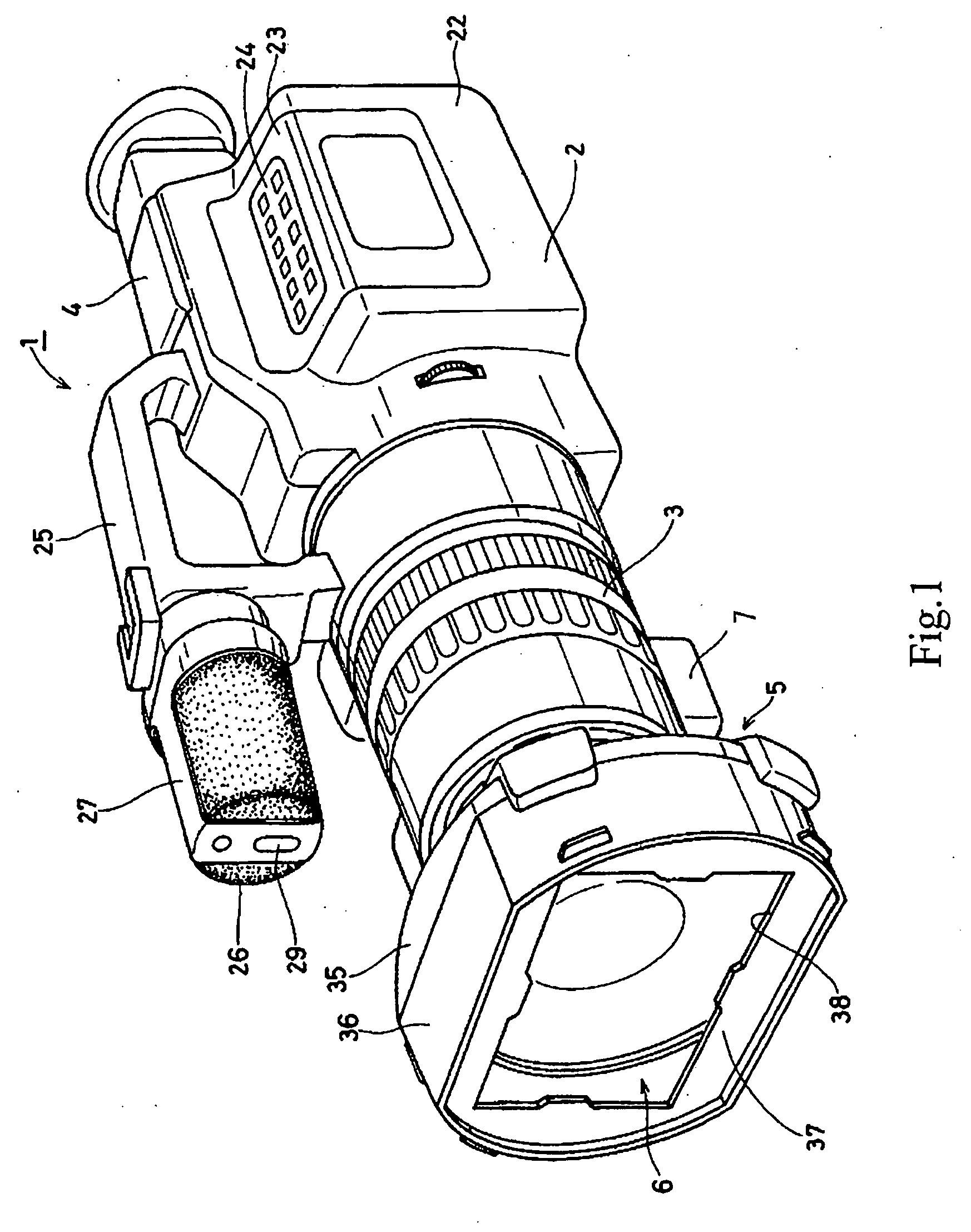
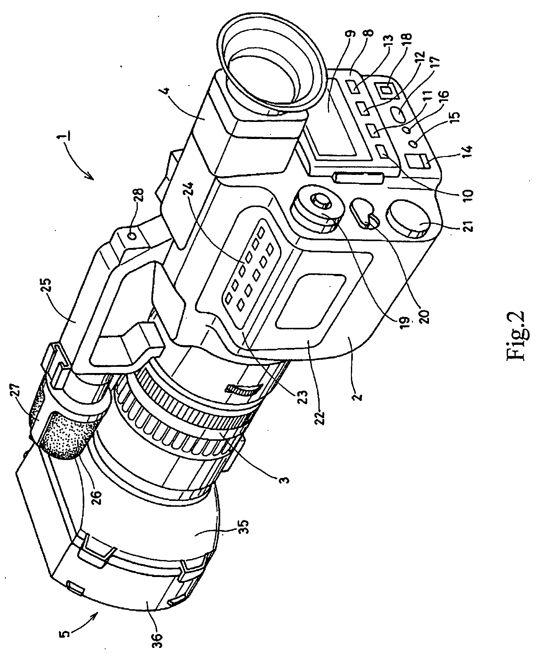
[0040] Now, an embodiment of the present invention will be described below referring to FIGS. 1 to 3. FIGS. 1 and 2 show the appearance of a video camera 1 according to this embodiment, in which a VTR mechanism, a battery as a power supply, and the like are incorporated in a main body 2, a shooting lens 3 is mounted on the front side, and a view finder 4 is provided on the rear half side in the state of being flat-layable and raisable to the rear side.

[0041] A lens hood 5 is mounted on the front side of the shooting lens 3 constituting an optical system in the video camera 1, through an adapter 7 shown in FIG. 3, and a conversion lens 6 can be detachably mounted inside the lens hood 5. The configurations of the lens hood 5 and the conversion lens 6 will be described in detail later.

[0042] A lid 8 for op...


PUM


Abstract

An image pickup apparatus is provided. The image pickup apparatus permitting a conversion lens to be mounted and dismounted, wherein a lens hood is composed of a base portion on the mounting side and a tubular portion on the front side, the base portion and the tubular portion are detachably coupled to each other, and another lens is contained in the inside of the lens hood when the another lens is mounted on the front side of an optical system, whereby even when the conversion lens is being used, the lens hood can be used as it is, and the incident light contracting function of the lens hood can be maintained.

Description

CROSS REFERENCE TO RELATED APPLICATION [0001] The present application claims priority to Japanese Patent Document No. 2003-353684 filed on Oct. 14, 2003, the disclosure of which is herein incorporated by reference. BACKGROUND OF THE INVENTION [0002] The present invention relates to an image pickup apparatus, particularly to an image pickup apparatus in which a lens hood is mounted on the front side of an optical system. [0003] When a point light source is put in an object at the time of shooting by a video camera, non-imaging light reflected by an air-glass joint plane of a shooting lens or the like reaches the image pickup screen to form irregular light spots, leading to the generation of flare and to a trouble in image pickup. [0004] Therefore, it has been an ordinary practice to mount a lens hood on the front side of the shooting lens of a video camera so as to prevent the generation of flare at the time of shooting. However, where the peripheral surface of the lens hood is long ...

Claims


Application Information

Patent Timeline
Patent Type & Authority Applications(United States)
IPC IPC(8): G02B21/00G02B7/02G02B7/14G02B27/00G03B11/04G03B17/12H04N5/225
CPCG02B7/14H04N5/2254G03B11/04G02B27/0018G03B11/041G03B11/045H04N23/55
Inventor SAKURAI, NOBUMASAYAMADA, YUKIOTSUKAMOTO, KAIZO
Owner SONY CORP
Learn More