Automatic defective product removing device for chip detection

A chip detection and rejection device technology, which is applied in the cleaning method using gas flow, transportation and packaging, cleaning method and utensils, etc., can solve the problems of chip surface adhesion, the collection box does not have a dust collection function, and chip damage.

Pending Publication Date: 2022-01-21
蓝芯存储技术(赣州)有限公司
View PDF1 Cites 0 Cited by
  • Summary
  • Abstract
  • Description
  • Claims
  • Application Information

AI Technical Summary

Problems solved by technology

[0004] However, the technical solution provided by this patent does not have the dust collection function for the collection box. When the defective products are blown out by the blowing device on the chip placement table, the external dust and impurities are easily blown together with the chips to the collection tube through the collection tube. In the box, if the dust in the collection box is not collected for a long time, there will be too much dust and impurities on the surface of the collected chip, which will cause damage to the chip.

Method used


Image

  • Automatic defective product removing device for chip detection
  • Automatic defective product removing device for chip detection
  • Automatic defective product removing device for chip detection

Examples


Embodiment 1

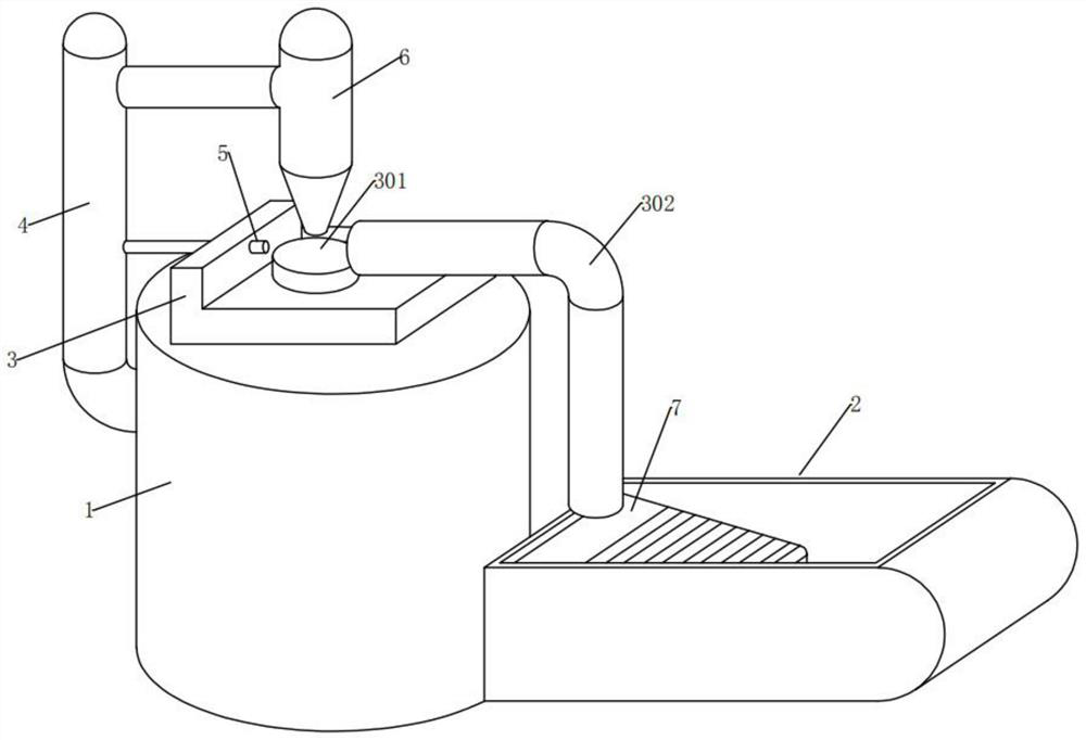
[0045] see Figure 1-3 , in an embodiment of the present invention, a device for automatically rejecting defective products for chip detection, comprising

[0046] Chip testing platform 1, a bracket 3 is fixedly installed at the center of the top of the chip testing platform 1, and the appearance of the bracket 3 is in the shape of "┗" in a longitudinal section, and a chip placement platform 301 is fixedly installed at the center of the top outer surface of the bracket 3 ;

[0047] The support 3 here is provided for the convenience of arranging the chip placement table 301, the collection pipe 302 and the air blowing device 5;

[0048] The collection box 2 is fixedly installed at the bottom of the right end of the chip testing platform 1. The collection box 2 is hollow inside, open up and closed down, and has a straight left and right convex shape;

[0049] The collection box 2 here is to collect dust for the convenience of accommodating defective chips and dust collection c...

Embodiment 2

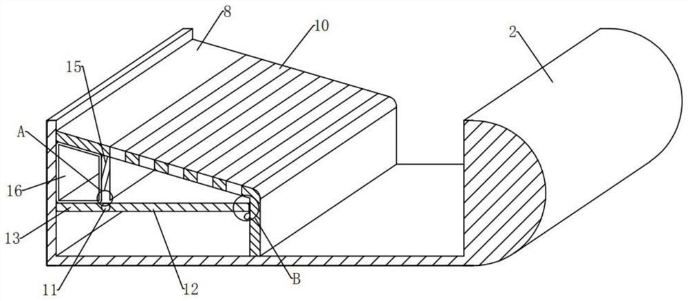
[0061] see Figure 2-4 with Figure 7 Compared with Embodiment 1, the embodiment of the present invention differs in that: the dust extraction assembly 9 includes:

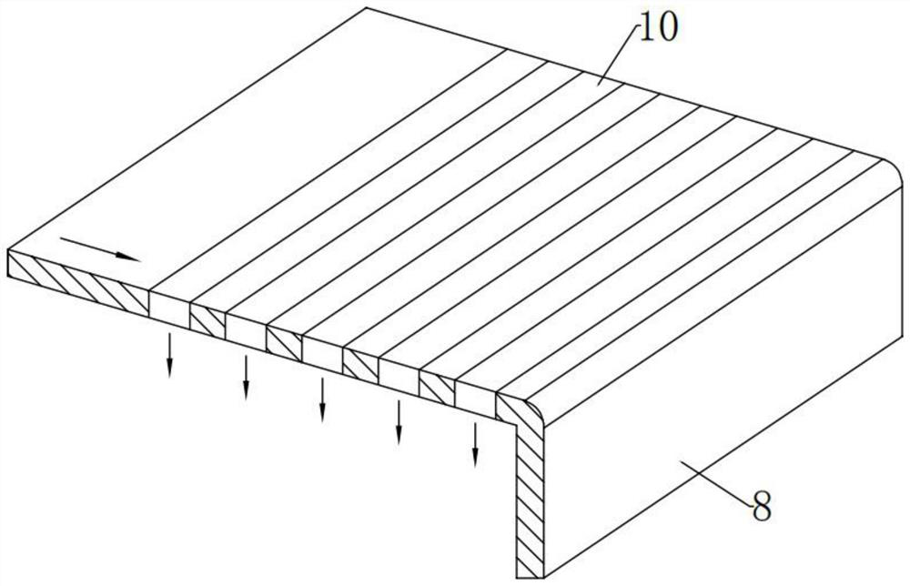
[0062] The dust guide net 10, the position between the top left to the right end of the dust guide slide plate 8 is in the front and rear horizontal direction and is arranged in a row with several through holes penetrating up and down. The through holes are embedded with a dust guide net 10, and the dust guide net 10 Under normal conditions in maximum stretch;

[0063] The dust guide net 10 here is to facilitate the chip defective products falling through the outlet of the tail end of the collection pipe 302 to collect dust through the dust guide net 10 during the process of sliding down the dust guide slide 8. A plurality of dust guide nets 10 can reduce the amount of dust adhered to the surface of defective chips collected at the lower right end of the collection box 2 .

[0064] In the embodiment of the pres...

Embodiment 3

[0073] see figure 2 , Figure 5-7 Compared with Embodiment 1, the embodiment of the present invention differs in that: the dust soaking assembly 14 includes:

[0074] Limiting plate 15, the position of the left end of the bottom side outer surface of the dust guide slide plate 8 is fixedly installed in the vertical direction of the limiting plate 15. The appearance of 15 is a parallelogram shape on a longitudinal section, and the bottom end of the limiting plate 15 is high in the left and low in the right, and the bottom end of the limiting plate 15 is located directly above the rotating shaft 11 and there is a distance between them;

[0075] The limiting plate 15 here is for the convenience of limiting and adorning the air bag 16. After the clockwise rotation of the right plate 12 and the left plate 13, the air bag 16 can be extruded and the clear water in it can be exported to soak dust.

[0076] In the embodiment of the present invention, the dust soaking assembly 14 als...


PUM


Abstract

The invention provides an automatic defective product removing device for chip detection, which comprises a chip detection table, a bracket is fixedly arranged at the center position of the top end of the chip detection table, the appearance of the bracket is L-shaped on a longitudinal section, and a chip placing table is fixedly arranged at the center position of the outer surface of the top side of the bracket; a collecting box is included and is fixedly mounted at the bottom of the right end of the chip detection table, and the collecting box is hollow inside, open at the upper part, closed at the lower part, straight at the left part and convex at the right part; and a dust collection assembly is also included. According to the automatic defective product removing device for chip detection, the collecting box can have a dust collecting function, when defective products are removed by blowing of a blowing device on the chip placing table, even if external dust impurities and chips are blown into the collecting box together through the collecting pipe, and dust in the collecting box can be collected and treated. And the phenomenon that too much dust and impurities adhere to the surfaces of the collected chips, and consequently the chips are damaged is avoided.

Description

technical field [0001] The invention relates to the technical field of chip detection, and more specifically, to an automatic rejecting device for defective products used in chip detection. Background technique [0002] Before the existing chip is manufactured and packaged, the manufacturer generally uses a pipeline-type detection device to detect the electrical characteristics of the chip. When unqualified products are detected, manual removal is required, which reduces the automation of chip production and the efficiency of manual removal of defective products. Low, it is also easy to produce deviations and pick wrong defective products, and the picked chips need to be manually checked again, which greatly reduces the efficiency of chip manufacturing. [0003] In view of the above problems, regarding the technical problems such as the low efficiency of chip defective product removal, after a large number of searches, the patent No. CN201520119741. Around the pipe, includi...

Claims


Application Information

Patent Timeline
Patent Type & Authority Applications(China)
IPC IPC(8): H01L21/67H01L21/677B07C5/02B07C5/34B07C5/36B08B5/02
CPCH01L21/67271H01L21/67288H01L21/67742B07C5/34B07C5/02B07C5/362B08B5/02B07C2301/0008
Inventor 庄晓鹏
Owner 蓝芯存储技术(赣州)有限公司
Why Eureka
Try Eureka