A drilling rig transformed from an excavator

A technology for excavators and drilling rigs, which is applied in the field of drilling rigs transformed by excavators, can solve problems such as affecting the efficiency of drilling operations, increasing the labor intensity of operators, and being unfavorable to environmental protection, so as to achieve efficient and reliable replacement of the brazing process, safe drilling operations and safety. Efficient and avoid the effect of dust

Active Publication Date: 2019-03-19
广西徐沃工程机械设备有限公司 +2
View PDF8 Cites 0 Cited by
  • Summary
  • Abstract
  • Description
  • Claims
  • Application Information

AI Technical Summary

Problems solved by technology

Existing drilling equipment has some defects in design, which are mainly manifested in: (1) When the parts on the pushing beam need to be repaired and maintained, there will be no support after the pushing beam is rotated to the horizontal position. It is beneficial to the safety of maintenance personnel; (2) The existing drilling rig propulsion beam adopts a channel steel structure, because the propulsion beam carries many parts, which is heavy and easy to deform; (3) The dust catcher is fixed at the lower end of the propulsion beam and cannot Adjust the position flexibly. During the drilling operation, under the action of the impact force, there will be a large gap with the drilling hole plane, and the dust leakage will be large, which is not conducive to environmental protection; (4) The replacement of the existing drilling rig drill rod is manual method, which not only affects the efficiency of the drilling operation, but also increases the labor intensity of the operator; (5) The existing rock drill push trolley and the push beam are generally connected by a sliding connection, and the contact surface of the sliding connection is relatively large. During the running process, the resistance received by the propelling trolley is relatively large, which increases the energy consumption of the power source

Method used


Image

  • A drilling rig transformed from an excavator
  • A drilling rig transformed from an excavator
  • A drilling rig transformed from an excavator

Examples


Embodiment Construction

[0032] The present invention will be further described below in conjunction with accompanying drawing.

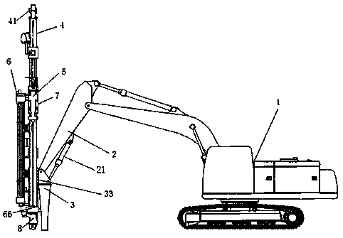
[0033] Such as Figure 1-9 As shown, a drilling rig transformed from an excavator includes an excavator body 1, an excavator arm 2 and a drilling rig working part. Rotate around the axis of the shaft.

[0034] The working part of the drilling rig includes a long maintenance work device 3 and a drill pipe column assembly, the upper end of the maintenance work device 3 is installed on the lower end of the excavator arm 2 through a rotating shaft, and the excavator arm 2 A hydraulic cylinder 21 is installed on the top, and the cylinder body of the hydraulic cylinder 21 is fixed on the excavator forearm 2, and the piston rod of the hydraulic cylinder 21 is connected with the top of the maintenance work device 3;

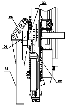
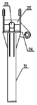
[0035] The drill pipe column assembly is installed on the maintenance work device 3 through the installation shaft 33, and the swing cylinder 32 is connected betwee...


PUM


Abstract

The invention discloses a drilling machine formed through transformation of an excavator. The drilling machine comprises an excavator body, an excavator forearm and a drilling machine working portion, wherein the drilling machine working portion replaces a bucket, is installed at the lower end of the excavator forearm through a rotary shaft, and can rotate with the axial direction of the rotary shaft as a circle center; the drilling machine working portion comprises a long maintenance working device and a drilling rod stand column assembly; the upper end of the maintenance working device is installed at the lower end of the excavator forearm through the rotary shaft; a hydraulic cylinder is installed on the excavator forearm, a cylinder body of the hydraulic cylinder is fixed to the excavator forearm, and a piston rod of the hydraulic cylinder is connected with the upper portion of the maintenance working device; and the drilling rod stand column assembly is installed on the maintenance working device through an installation shaft, a swinging oil cylinder is connected between the drilling rod stand column assembly and the maintenance working device, and through telescoping of the swinging oil cylinder, the drilling rod stand column assembly rotates with the axial direction of the installation shaft as a circle center.

Description

technical field [0001] The invention relates to the technical field of mechanical engineering, in particular to a drilling rig transformed from an excavator. Background technique [0002] The main function of the drilling rig is to drive the drilling tool to break the rock at the bottom of the hole, and to lower or raise the drilling tool in the hole. It can be used to drill cores, ore cores, cuttings, gaseous samples, liquid samples, etc., to ascertain the conditions of underground geology and mineral resources. At present, drilling rigs are widely used in blast hole drilling operations in mines, coal, building materials, hydropower construction, highways, railway engineering and other earthwork engineering. Existing drilling equipment has some defects in design, which are mainly manifested in: (1) When the parts on the pushing beam need to be repaired and maintained, there will be no support after the pushing beam is rotated to the horizontal position. It is beneficial t...

Claims


Application Information

Patent Timeline
Patent Type & Authority Patents(China)
IPC IPC(8): E21B7/02E21B25/00
CPCE21B7/025E21B25/00
Inventor 姜金堂班华电
Owner 广西徐沃工程机械设备有限公司
Why Eureka
Try Eureka