

Raw material screening device for concrete production and processing
A screening device and concrete technology, which is applied in the direction of using liquid separation agent, filter screen, solid separation, etc., can solve the problems of excessive dust, polluting the working environment, and the fixed cylinder does not have the function of dust collection, etc.
- Summary
- Abstract
- Description
- Claims
- Application Information
AI Technical Summary
Problems solved by technology
Method used
Image

Examples
Embodiment 1
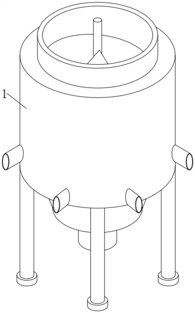
[0048] see Figure 1-5 , in an embodiment of the present invention, a raw material screening device for concrete production and processing, comprising
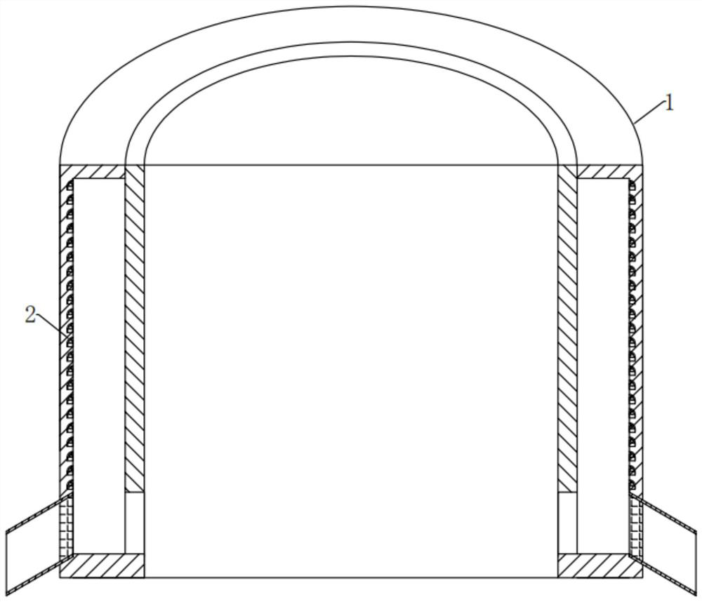
[0049] The fixed cylinder 1, the internal position of the inner wall of the longitudinal side of the fixed cylinder 1 is arranged vertically in an up-and-down vertical direction and surrounded by a number of dust collection components 2 that can collect dust;
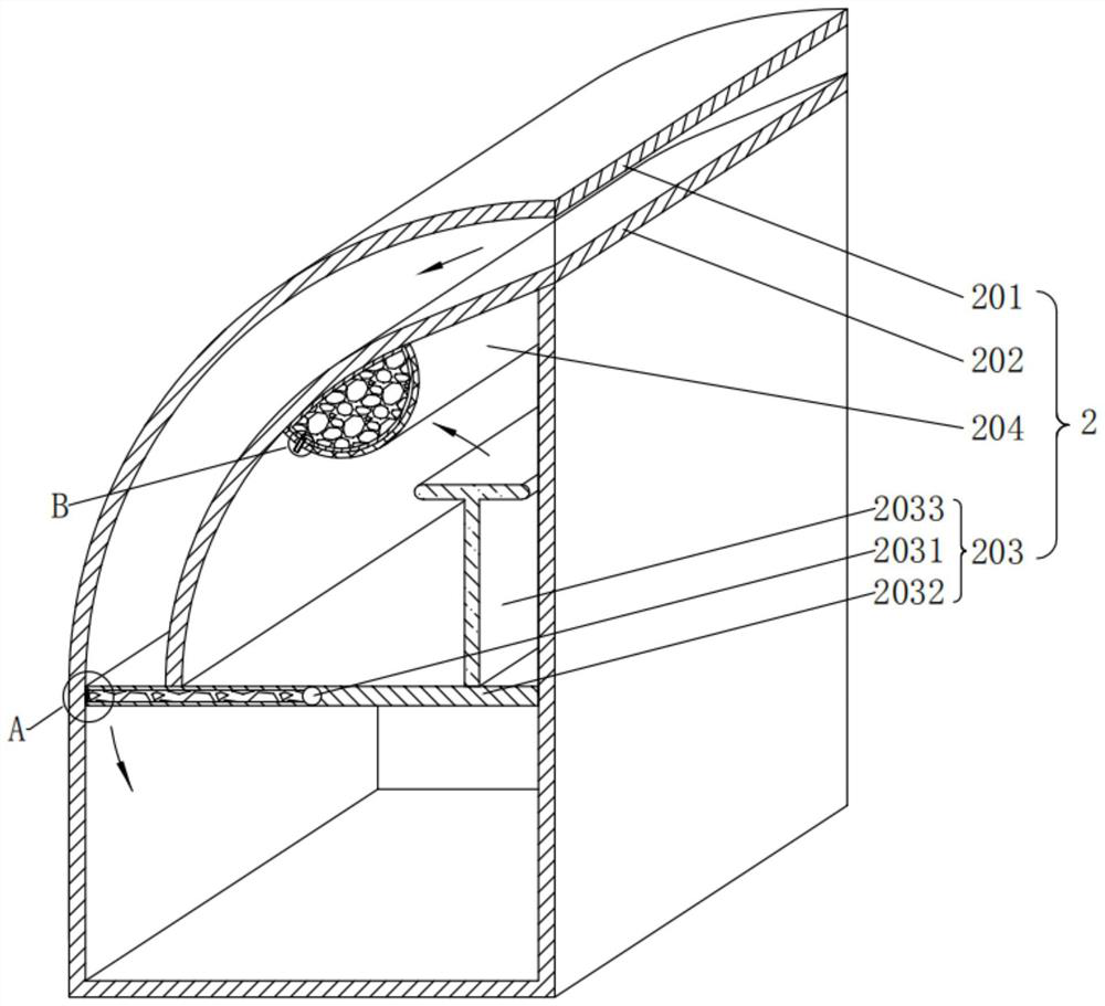
[0050] The dust collection assembly 2, the dust collection assembly 2 includes a dust collection tank 201, a dust guide plate 202, a dust closing assembly 203 that can seal the collected dust to prevent it from being raised, and can humidify the collected dust to isolate it The dust-absorbing component 204;
[0051] The dust collecting tank 201 is placed vertically and vertically in equal rows, surrounding and embedded in the inner position of the longitudinal side inner wall of the fixed cylinder 1;
[0052] A dust guide plate 202 is fixedly installed between the fro...
Embodiment 2
[0061] see image 3 , Figure 6-7 Compared with Embodiment 1, this embodiment of the present invention differs in that: the dust sealing assembly 203 includes a rotating shaft 2031 , a horizontal plate 2032 and a push plate 2033 .
[0062] In the embodiment of the present invention, a rotating shaft 2031 is installed in the middle of the lower end of the front and rear inner walls of the dust collection tank 201 to rotate in the front and rear horizontal direction;
[0063] The outer surface of the rotating shaft 2031 is surrounded by a horizontal plate 2032 fixedly installed. The horizontal plate 2032 is in a horizontal static equilibrium state under normal conditions. close, the outer surface of the top left end of the horizontal plate 2032 is in close contact with the outer surface of the bottom end of the dust guide plate 202 under normal conditions;
[0064] The horizontal plate 2032 here is to facilitate the use of the principle of leverage. When the dust slides all th...
Embodiment 3
[0073] see image 3 , Figure 8-9 Compared with Embodiment 1, the embodiment of the present invention differs in that: the dust-absorbing assembly 204 includes a support net 2041 , a large air bag 2042 and a duct 2043 .
[0074] In the embodiment of the present invention, a support net 2041 is fixedly installed at the upper end of the inner wall of the dust guide plate 202;
[0075] The support net 2041 here is to support the large air bag 2042, preventing the bottom end of the large air bag 2042 with clear water from being heavily stretched;
[0076] A large air bag 2042 is embedded between the inner side of the support net 2041 and the inner wall of the dust guide plate 202, and the inner position of the large air bag 2042 is also pre-installed with clean water;
[0077] Here, the large air bag 2042 and the clear water in it are for the convenience of utilizing the principle of negative pressure. After the horizontal plate 2032 rotates, the push plate 2033 is squeezed onto...
PUM
 Abstract
Description
Claims
Application Information