
Printer

a printing medium and printing plate technology, applied in the field of printing plates, can solve the problems of increasing design troubles of design engineers, affecting the quality of printed materials, and complicated cover shapes, so as to prevent the occurrence of jamming of printing media, reduce the vertical movement of printing media, and avoid the effect of increasing manufacturing costs

Active Publication Date: 2006-01-12
BROTHER KOGYO KK
View PDF3 Cites 21 Cited by
  • Summary
  • Abstract
  • Description
  • Claims
  • Application Information

AI Technical Summary

Benefits of technology

[0007] However, the thermal printer disclosed in the '234 publication needs be designed in minute detail about the shape and arrangement of the plurality of projecting pieces with high precision. This printer further needs a space for the projecting pieces, which results in a complicated shape of the cover. This may increase design troubles to design engineers and a production cost.
[0008] The present invention has been made in view of the above circumstances and has an object to overcome the above problems and to provide a printer with a simple structure capable of smoothly guiding and discharging a printing medium to and through an outlet of a feeding path while preventing the printing medium from becoming curled or curved in the feeding path to avoid jamming.

Problems solved by technology

This printer further needs a space for the projecting pieces, which results in a complicated shape of the cover.
This may increase design troubles to design engineers and a production cost.

Method used


Image

  • Printer
  • Printer
  • Printer

Examples


Embodiment Construction

[0042] A detailed description of a preferred embodiment of a label printer for a printer embodying the present invention will now be given referring to the accompanying drawings.

[0043] Firstly, a schematic structure of the label printer in the present embodiment will be described with reference to FIGS. 1 to 7.

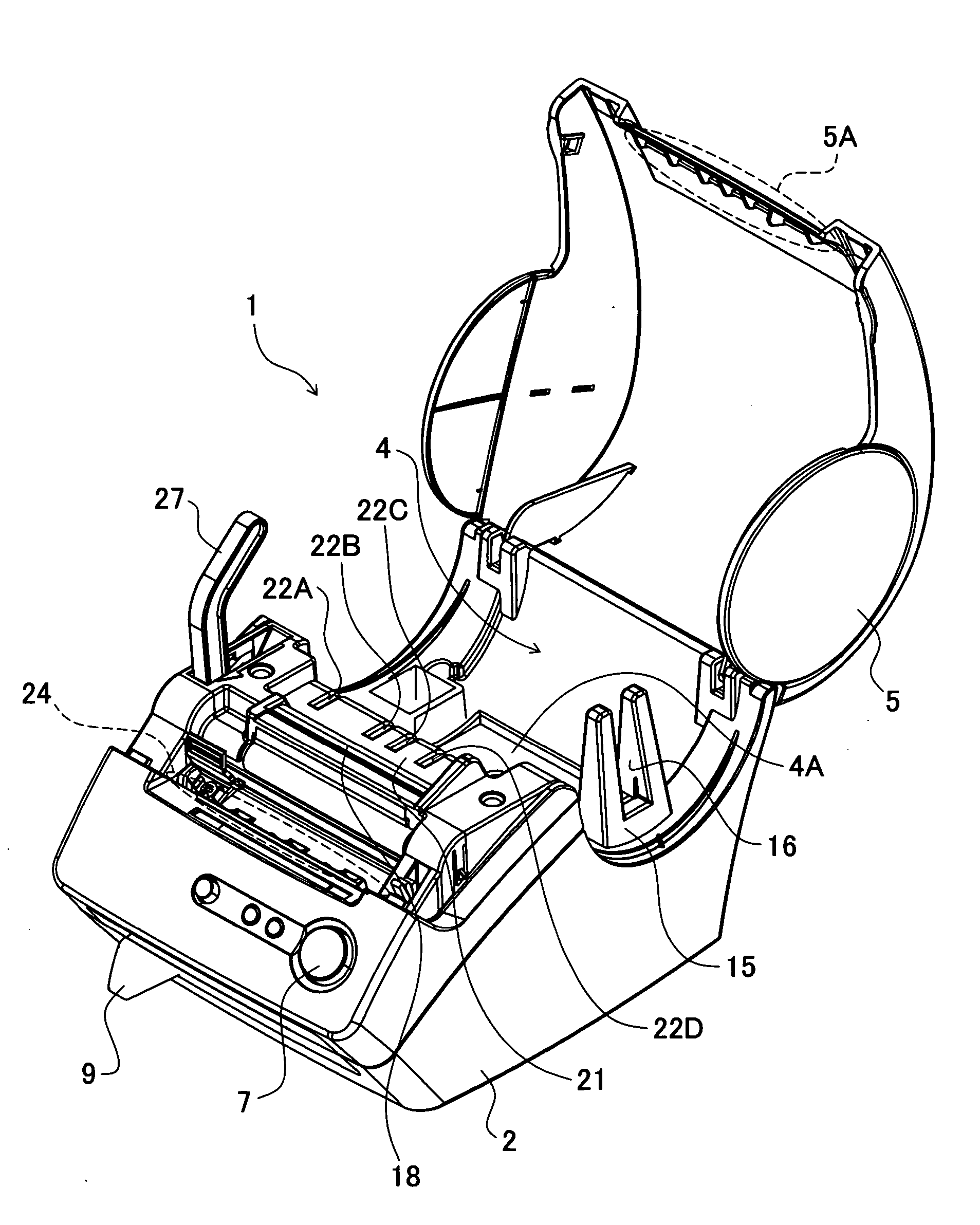
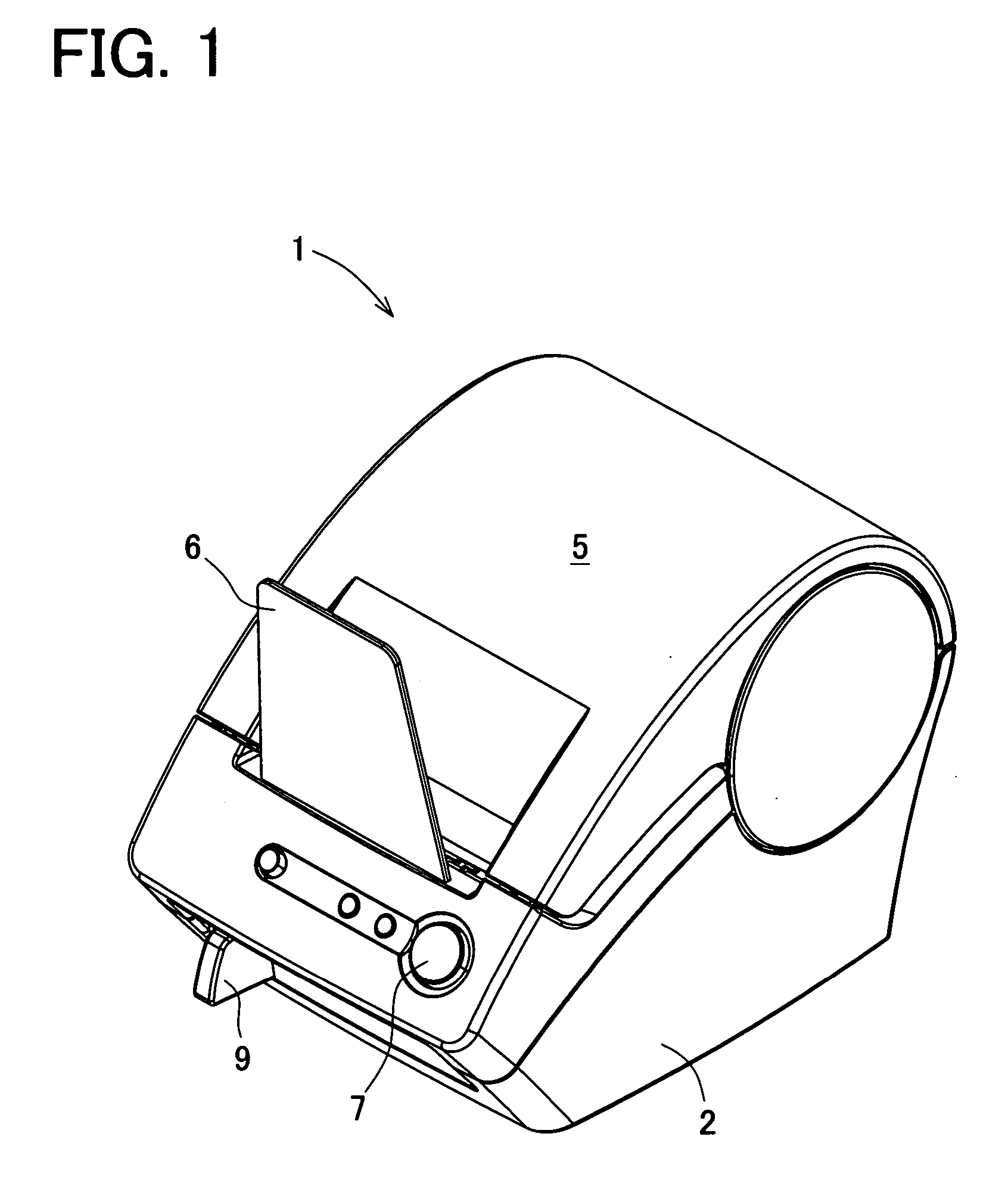
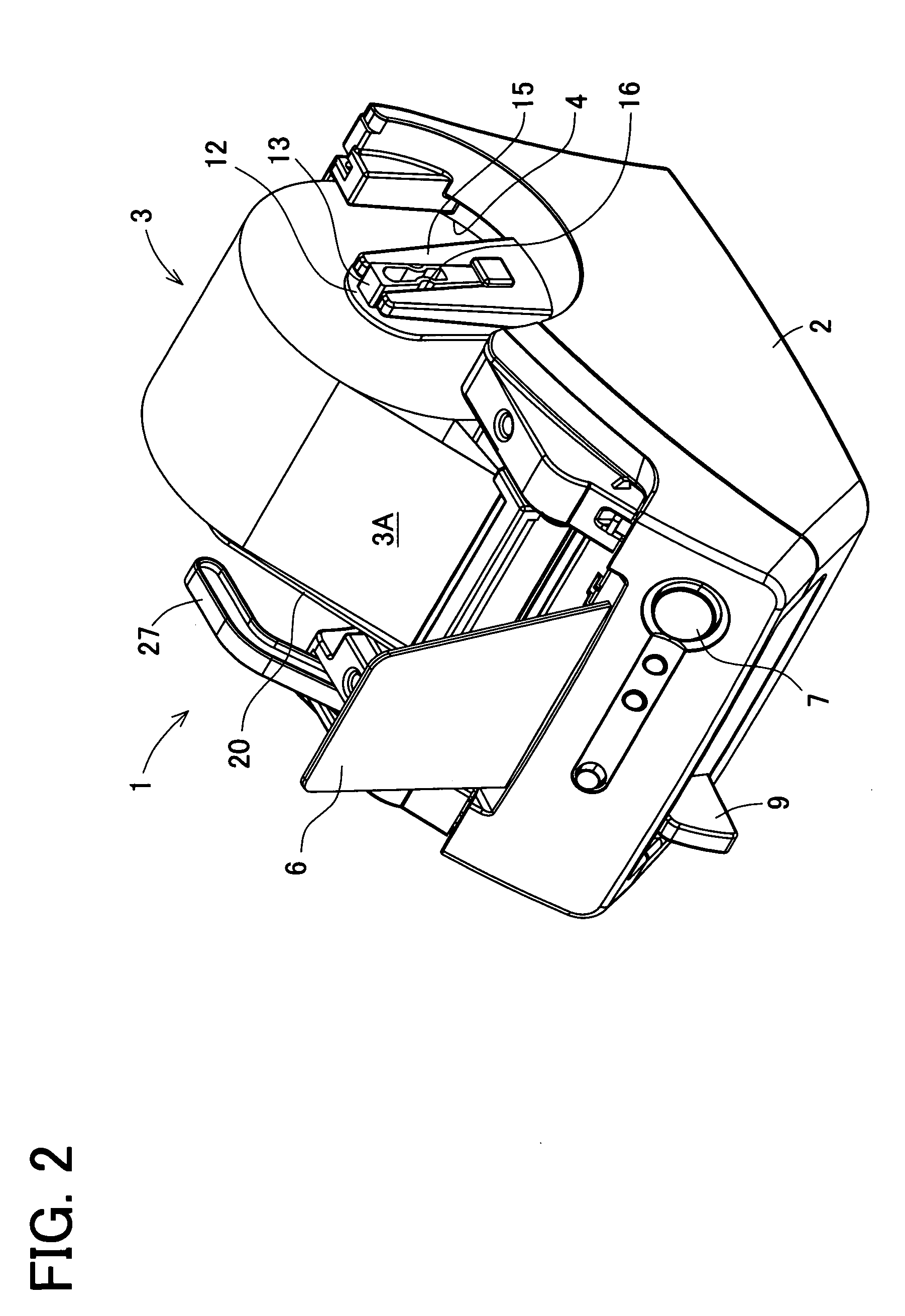
[0044] As shown in FIGS. 1 to 3, a label printer 1 includes a housing (main body) 2, a top cover 5 (a first feeding path member) made of transparent resin attached to the housing 2 at a rear upper edge, a tray 6 made of transparent resin disposed in a standing position to face to a substantially front center of the top cover 5, a power button 7 placed in front of the tray 6, a cutter lever 9 movable side to side to horizontally move a cutter unit 8 (see FIG. 7), and others. The top cover 5 is freely opened and closed, thereby covering an upper part of a roll sheet holder storage part (hereinafter, a “holder storage part”) 4 which is a space for receiving a roll sheet holder ...


PUM


Abstract

A top cover and a guide member form a discharge port. A plurality of guide ribs is provided on an edge portion of the top cover. A plurality of projecting pieces is provided on a guide member at positions not to face to the guide ribs. These guide ribs and projecting pieces are used for guiding a roll sheet to a discharge port. At least one of the guide ribs is provided with an extended portion extending upstream in a feeding direction to prevent the roll sheet 3A from curving in a direction vertical to the feeding direction. Thus, the inability to discharge the roll sheet can be avoided.

Description

BACKGROUND OF THE INVENTION [0001] 1. Field of the Invention [0002] The present invention relates to a printer capable of smoothly outward discharging a printing medium being transported after printing data requested by a user has been printed thereon and capable of preventing troubles leading to the inability to discharge paper, i.e., jamming, due to curving of the printing medium. [0003] 2. Description of Related Art [0004] In a conventional printer, a printing medium tends to be bent because a leading end of the printing medium comes into contact with an outlet portion of a feeding path when the printing medium is transported to the outside. This would cause the inability to discharge paper (jamming). To prevent such jamming, Japanese patent application laid-open publication No. H6(1994)-13234 discloses a technique for smoothly discharging a printing medium by providing a projecting piece in a feeding path along which the printing medium is moved. [0005] A thermal printer disclos...

Claims


Application Information

Patent Timeline
Patent Type & Authority Applications(United States)
IPC IPC(8): B41J11/70B41J15/04
CPCB41J11/0015B41J15/046B41J15/02B41J11/006
Inventor SAGO, AKIRAKASUGAI, ATSUSHIFUNATO, NOBUHIKO
Owner BROTHER KOGYO KK
Learn More