
Female terminal fitting

a terminal fitting and female technology, applied in the field of female terminal fittings, can solve the problems of reducing productivity and reducing the strength of the female terminal fitting, and achieve the effects of reducing the strength of the entire connection portion, and reducing the size of the connection portion

Inactive Publication Date: 2006-01-12
SUMITOMO WIRING SYST LTD
View PDF12 Cites 8 Cited by
  • Summary
  • Abstract
  • Description
  • Claims
  • Application Information

AI Technical Summary

Benefits of technology

[0011] The concavities formed on the side surfaces of the connection portion enable a connection portion that has a narrow external width, while also having large clearance outward from the side surfaces of the tab. The concavities are formed only on part of side surfaces of the connection portion. Thus, a decrease in the strength of the entire connection portion can be minimized. The large clearance avoids the need for a higher accuracy in manufacturing both male and female terminal fittings. Thus, productivity will not deteriorate.
[0012] The above-described female terminal fitting is made compact without deteriorating the strength and productivity.

Problems solved by technology

However, there is a fear that the strength of the female terminal fitting will decrease too much.
However, a smaller clearance requires the male and female terminal fittings to be manufactured at high accuracy, thus reducing productivity.

Method used


Image

  • Female terminal fitting
  • Female terminal fitting
  • Female terminal fitting

Examples


Embodiment Construction

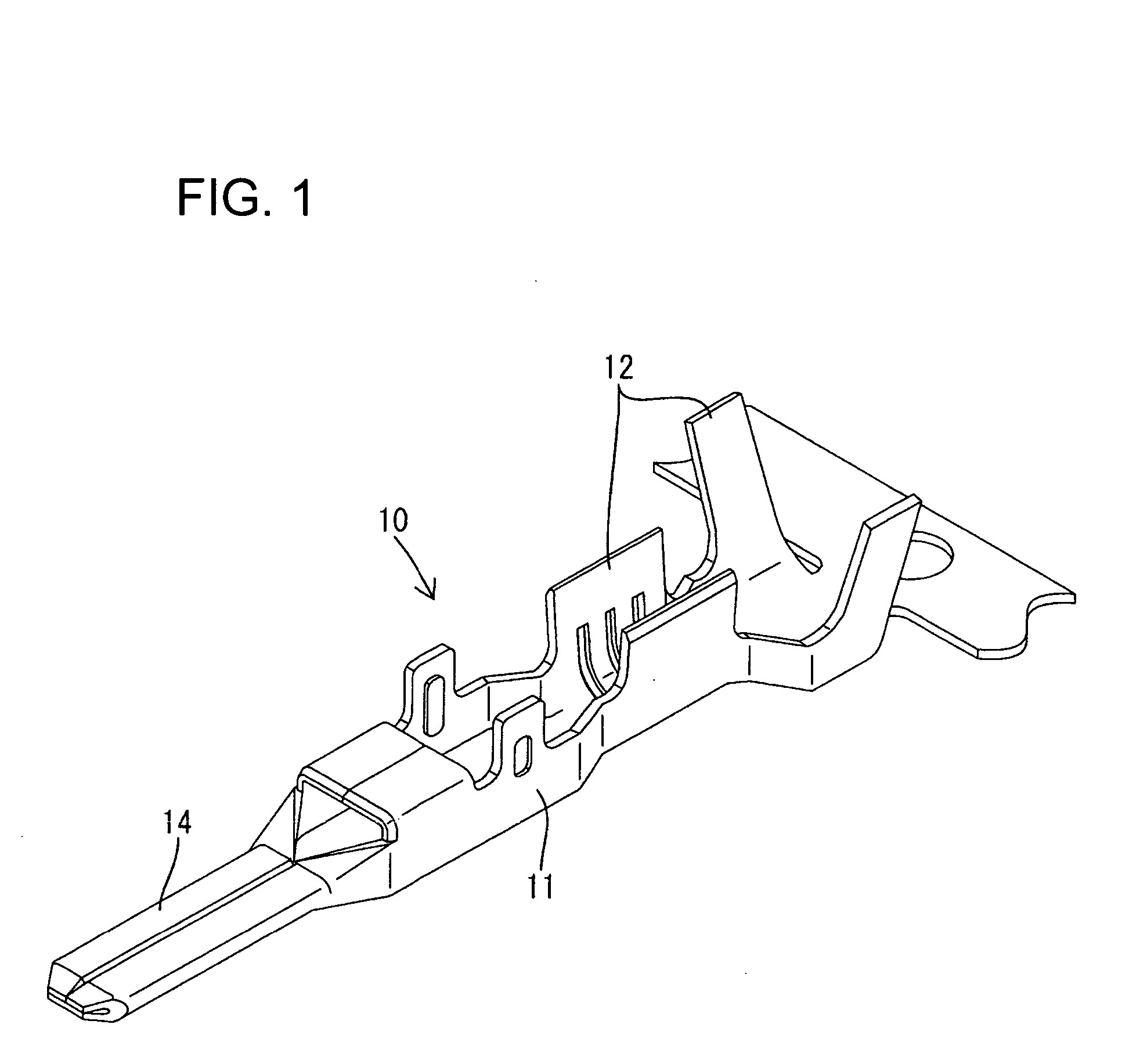
[0023] A metal fitting according to the invention has a male terminal fitting 10 and a female terminal fitting 20, as shown in FIGS. 1-8A. The male terminal fitting 10 is formed by press working a metal plate having a high electrical conductivity. As shown in FIGS. 1 and 2, the male terminal fitting 10 has opposite front and rear ends and a body 11 between the ends. A barrel 12 is disposed rearward from the body 11 and is configured to be crimped to an end of an electric wire 40. A tab 14 is disposed forward of the body 11 and is dimensioned for connection with the female terminal fitting 20.

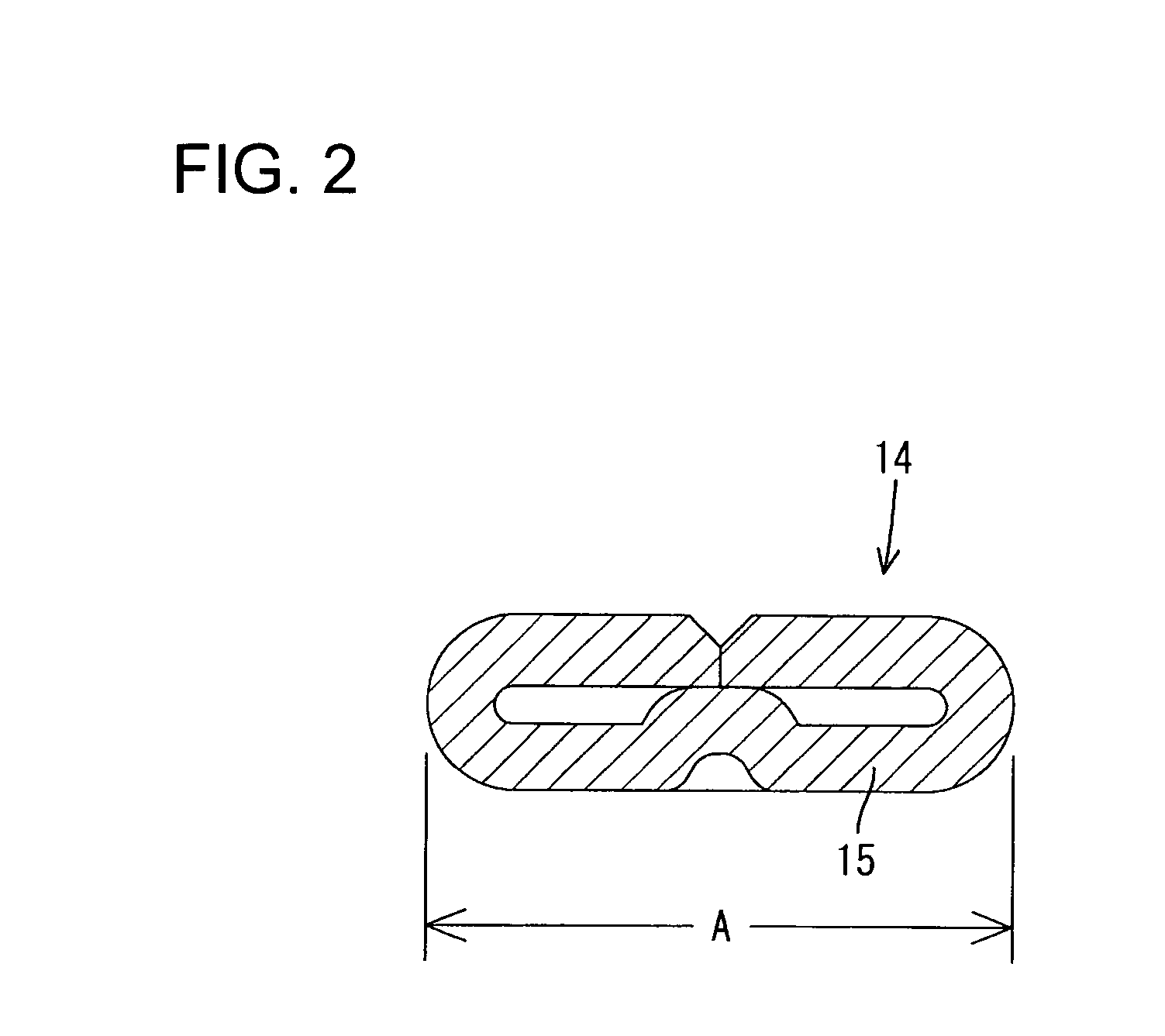
[0024] As shown in FIG. 2, the tab 14 is formed from a substrate 15, and half of the left and right sides of the substrate 15 are folded up to form a double-plate construction of width A. A front end of the tab 14 is tapered to guide more rearward portions of the tab 14 into the female terminal fitting 20.

[0025] The female terminal fitting 20 is formed into the configuration shown in FIGS. 3 t...


PUM


Abstract

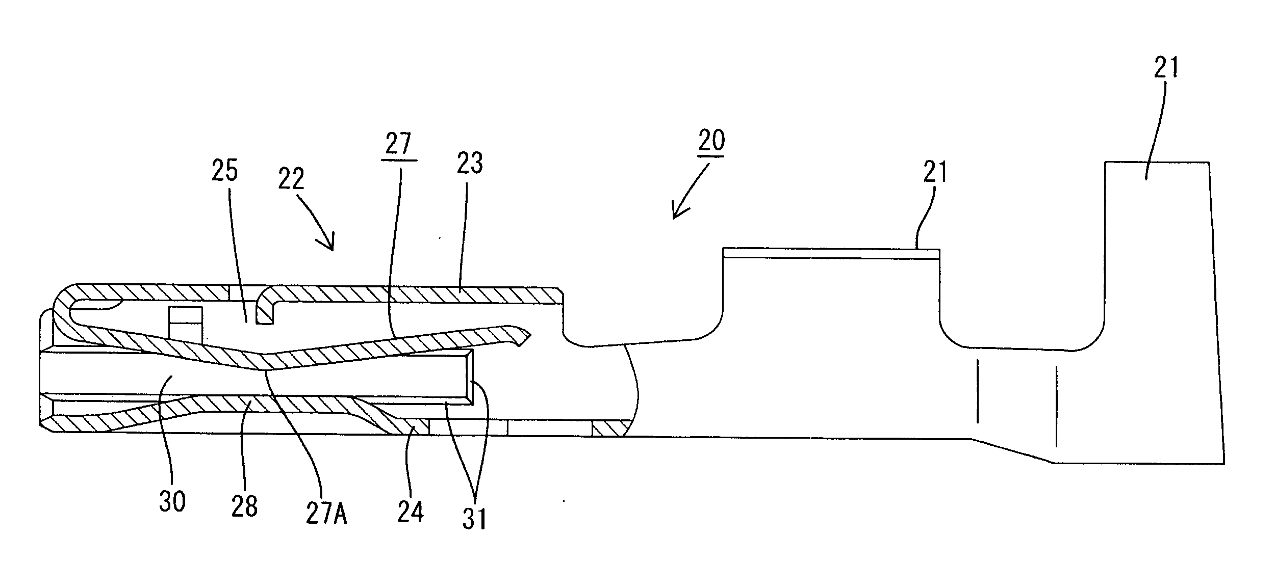
A female terminal fitting (20) has an approximately tubular connection portion (22) with an open front end for receiving a tab (14) of a male terminal fitting (10). Concavities (30) extend longitudinally in the connection portion (22) at positions opposed to side surfaces of the tab (14). The concavities (30) enable the outside width (W) of the connection portion (22) to be small while securing a large clearance (C) outward from the side surfaces of the tab (14). The concavities (30) do not significantly decrease the strength of the entire connection portion (22). Additionally, the large clearance (C) avoids the need for highly accurate manufacturing.

Description

BACKGROUND OF THE INVENTION [0001] 1. Field of the Invention [0002] The invention relates to a female terminal fitting. [0003] 2. Description of the Related Art [0004] U.S. Pat. No. 5,336,540 discloses a female terminal fitting that is fixed to an end of an electric wire. The female terminal fitting has a box-shaped connection portion with an open front end for receiving the tab of a male terminal fitting. An elastic contact piece is provided inside the female terminal fitting and elastically contacts the tab that has been inserted into the open front of the connection portion. Thus, an electrical connection is made between the tab of the male terminal fitting and the elastic contact piece of the female terminal fitting. [0005] There is a growing demand for miniature terminal fittings. However, the tab of the male terminal fitting must be sufficiently wide to achieve a reliable electrical connection between the male and female terminal fittings. Thus, options for miniaturization app...

Claims


Application Information

Patent Timeline
Patent Type & Authority Applications(United States)
IPC IPC(8): H01R11/22
CPCH01R43/16H01R13/113
Inventor NORO, YUTAKAISHIKAWA, RYOTAROKAWASE, HAJIME
Owner SUMITOMO WIRING SYST LTD
Learn More