
Method for controlling transmissions using both diversity and nondiversity transmission schemes

a transmission scheme and diversity technology, applied in the field of wireless communication, can solve the problems of small changes in differential propagation delay, large changes in the phase of individual waves, and significant differences in channel quality at the time of actual transmission

Inactive Publication Date: 2006-01-12
LUCENT TECH INC
View PDF7 Cites 51 Cited by
  • Summary
  • Abstract
  • Description
  • Claims
  • Application Information

AI Technical Summary

Benefits of technology

"The patent describes a method for transmitting and receiving information using a diversity scheme and a non-diversity scheme during different parts of a transmission period. This method ensures reliable and efficient communication by using multiple pilot signals. The technical effect of this patent is improved communication reliability and efficiency."

Problems solved by technology

Waves arriving at the MS in the downlink direction (at the BS in the uplink direction) experience constructive and destructive additions because of different phases of the individual waves.
This is due the fact that, at high carrier frequencies typically used in cellular wireless communication, small changes in the differential propagation delays introduce large changes in the phases of the individual waves.
At high mobile speeds, the channel quality at the time of actual transmission may be significantly different from the channel quality estimates due to channel quality feedback and / or processing delays.
For example, a system that requires the base station to dynamically switch between transmit diversity mode and no transmit diversity mode is highly complex to implement.
For example, when no transmit diversity is used for a transmission, total power is transmitted from a single antenna requiring larger capacity and more complex power amplifiers.
Additionally, pilot overhead is substantially increased due to constant transmissions of pilot symbols from each of the transmit antennas

Method used


Image

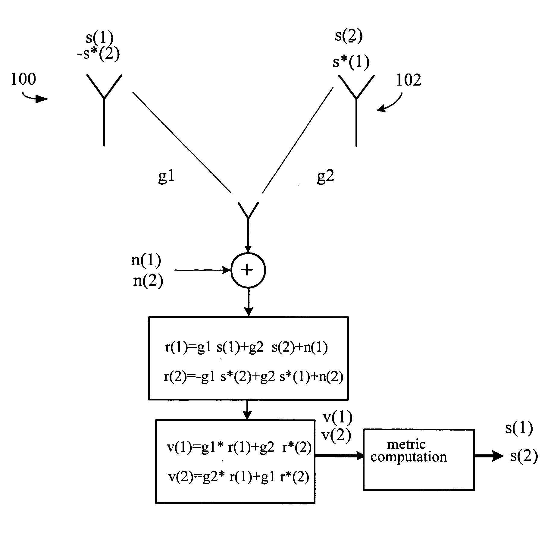
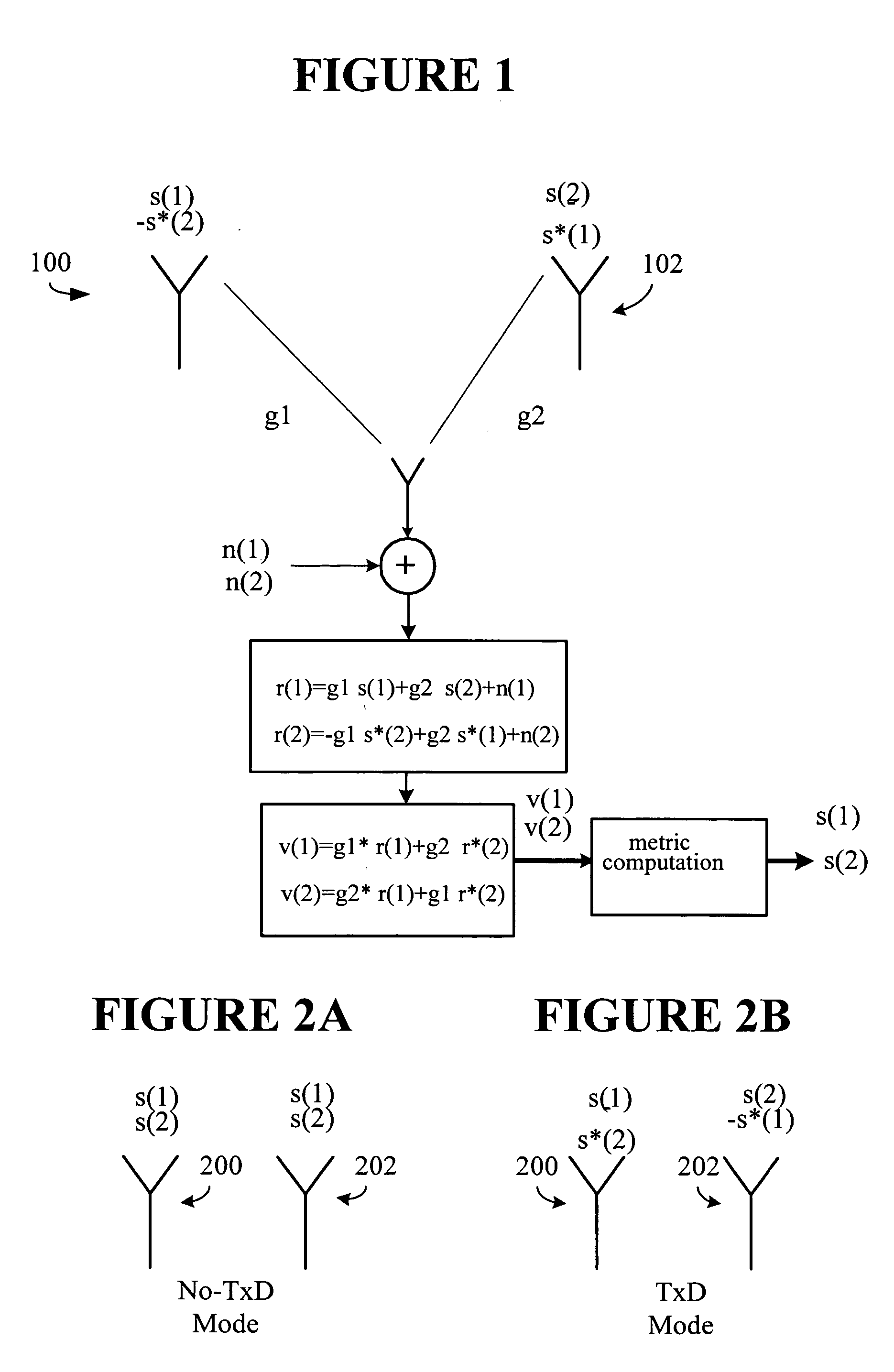
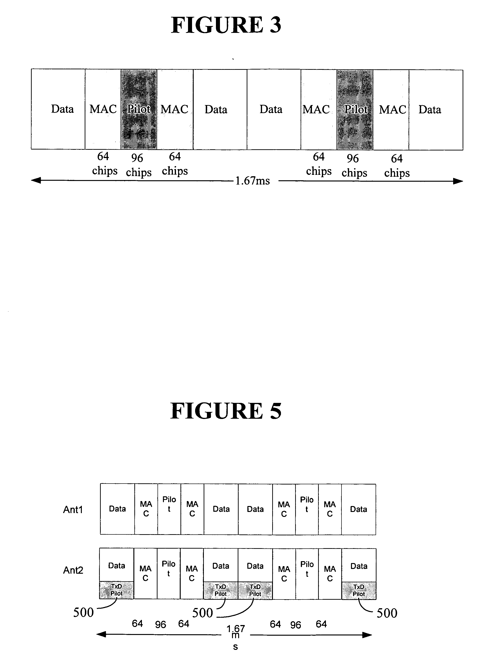
  • Method for controlling transmissions using both diversity and nondiversity transmission schemes
  • Method for controlling transmissions using both diversity and nondiversity transmission schemes
  • Method for controlling transmissions using both diversity and nondiversity transmission schemes

Examples


Embodiment Construction

[0025] Illustrative embodiments of the invention are described below. In the interest of clarity, not all features of an actual implementation are described in this specification. It will of course be appreciated that in the development of any such actual embodiment, numerous implementation-specific decisions may be made to achieve the developers' specific goals, such as compliance with system-related and business-related constraints, which may vary from one implementation to another. Moreover, it will be appreciated that such a development effort might be complex and time-consuming, but would nevertheless be a routine undertaking for those of ordinary skill in the art having the benefit of this disclosure.

[0026] The present invention describes a transmit diversity scheme where the transmission modes can be switched between transmit diversity mode and no transmit diversity mode. The total base station power is generally equally split between the transmit antennas regardless of whet...


PUM


Abstract

A wireless communications system is provided in which transmissions may be made in either a diversity mode or a non-diversity mode on a slot by slot basis. When transmitting in the diversity mode, separate pilot signals are delivered over a first and second antenna. When transmitting in the non-diversity mode, substantially identical pilot signals are delivered over the first and second antennas with available pilot power substantially equally distributed therebetween.

Description

BACKGROUND OF THE INVENTION [0001] 1. Field of the Invention [0002] This invention relates generally to telecommunications, and more particularly, to wireless communications. [0003] 2. Description of the Related Art [0004] A typical cellular radio system consists of a collection of fixed base stations (BS) that define radio coverage areas or cells. Typically, a non-line-of-sight (NLOS) radio propagation path exists between a base station and a mobile station (MS) due to natural and man-made objects that are situated between the base station and the mobile station. As a consequence, the radio waves propagate via reflections, diffractions and scattering. Waves arriving at the MS in the downlink direction (at the BS in the uplink direction) experience constructive and destructive additions because of different phases of the individual waves. This is due the fact that, at high carrier frequencies typically used in cellular wireless communication, small changes in the differential propag...

Claims


Application Information

Patent Timeline
Patent Type & Authority Applications(United States)
IPC IPC(8): H03C7/02H04L27/04H04B1/02
CPCH04B7/0613H04L1/0009H04W52/42H04L1/1812H04L1/0625H04B7/02H04L1/02
Inventor KHAN, FAROOQ ULLAHVISWANATHAN, HARISH
Owner LUCENT TECH INC
Learn More