Apparatus and method for proving the denial of a direct proof signature

Active Publication Date: 2006-01-12
INTEL CORP
View PDF47 Cites 47 Cited by
  • Summary
  • Abstract
  • Description
  • Claims
  • Application Information

AI Technical Summary

Problems solved by technology

In practice, the above-identified approach is problematic because it requires TTPs to be established.
Identifying and establishing various parties that can serve as TTPs has proven to be a substantial obstacle.

Method used


Image

  • Apparatus and method for proving the denial of a direct proof signature
  • Apparatus and method for proving the denial of a direct proof signature
  • Apparatus and method for proving the denial of a direct proof signature

Examples


Embodiment Construction

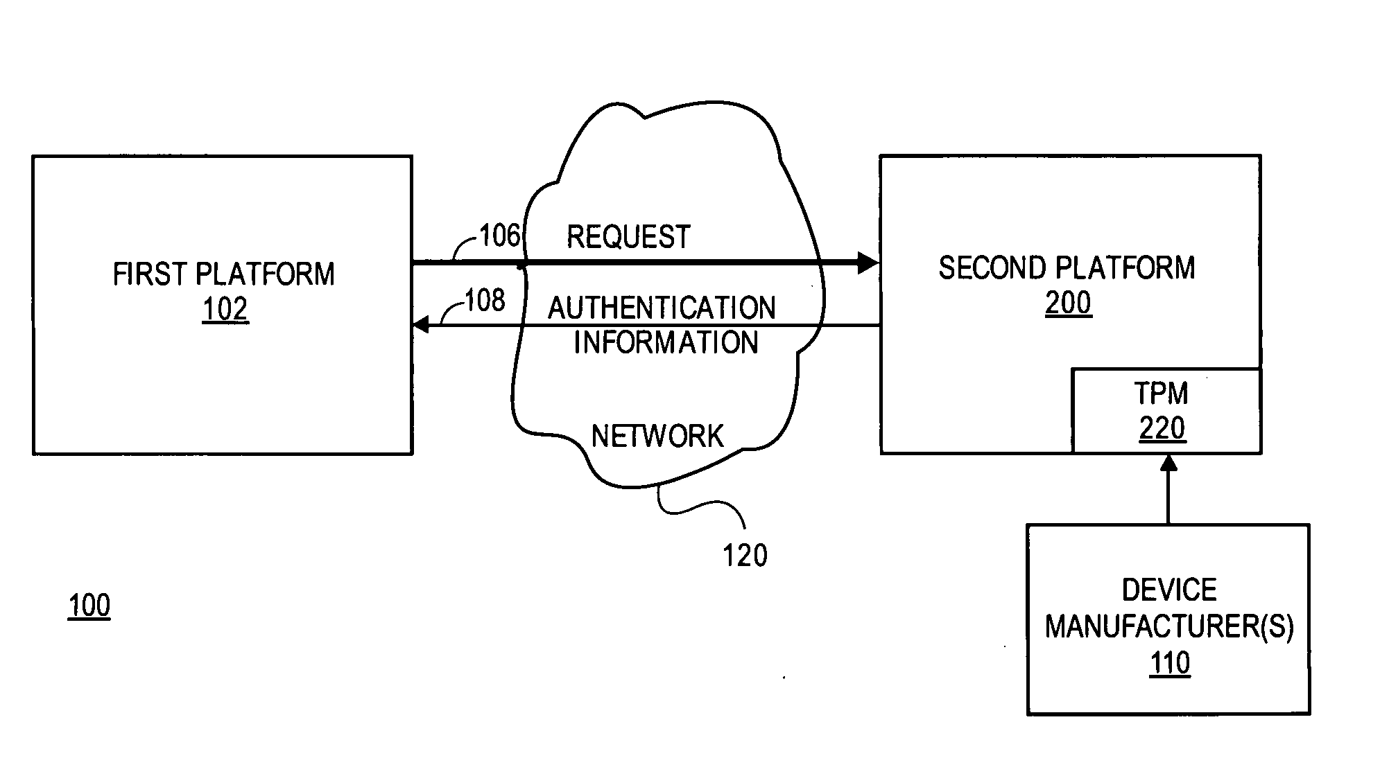
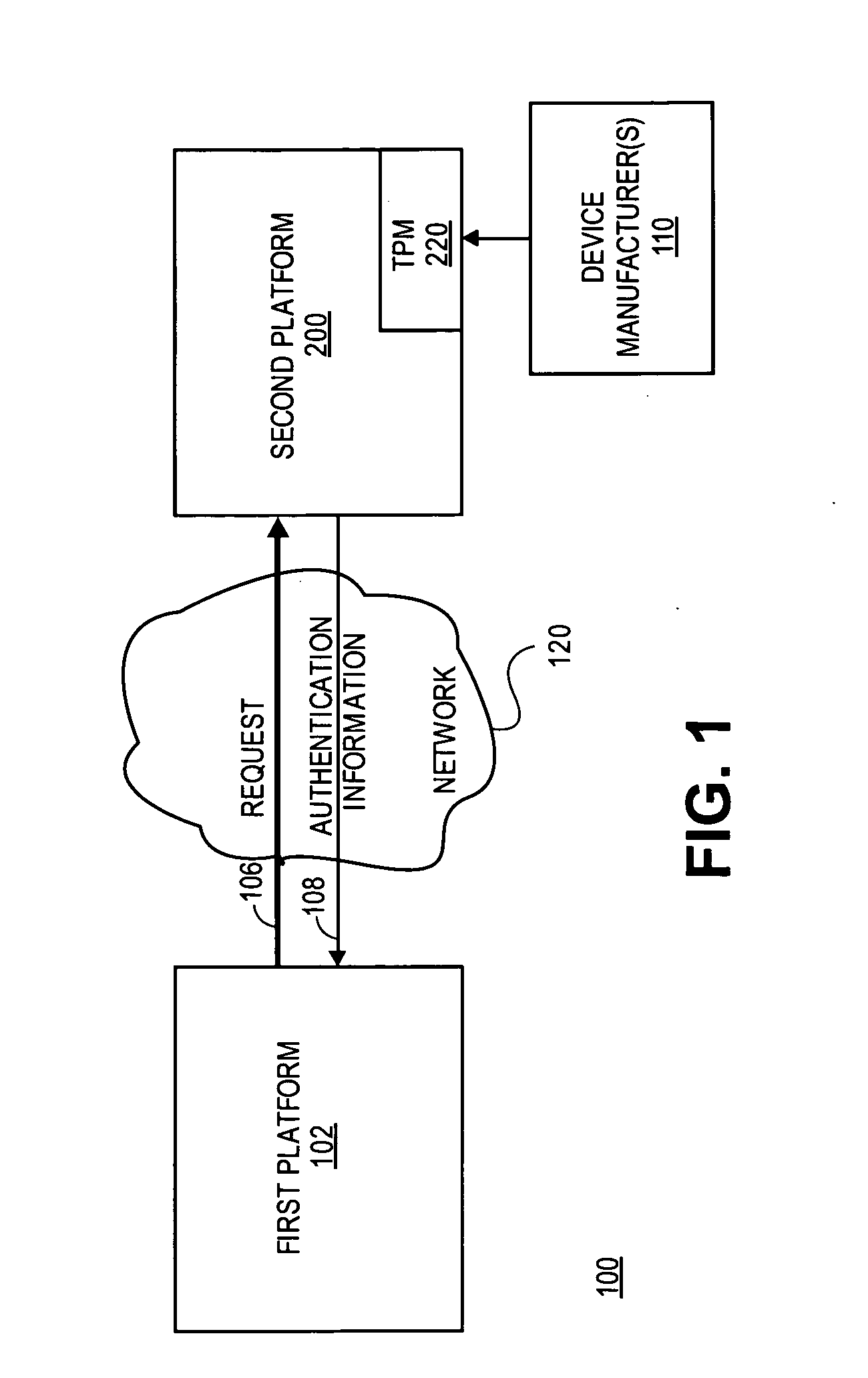
[0020] A method and apparatus for proving the denial of a direct proof signature are described. In one embodiment a trusted hardware device convinces a verifier of possessing cryptographic information without revealing unique, device identification information of the trusted hardware device or the cryptographic information. This is accomplished without the use of a Trusted Third Party (TTP). Rather, it is accomplished by a “direct proof” methodology in which computations by the TPM involve exponentiations using a cryptographic key as an exponent. In one embodiment, the trusted hardware device proves to a verifier that a digital signature used in the direct proof (“direct proof signature”) is based on an uncompromised cryptographic key.

[0021] In one embodiment, the verifier may issue a denial signature request to the trusted hardware device to prove that a cryptographic key held by the trusted hardware device was not used to form a direct proof signature suspected of being compromis...


PUM


Abstract

In some embodiments, a method and apparatus for proving the denial of a direct proof signature are described. In one embodiment, a trusted hardware device convinces a verifier that the trusted hardware device possesses cryptographic information without revealing unique, device identification information of the trusted hardware device or the cryptographic information. Once the verifier is convinced that the hardware device possesses the cryptographic information, the verifier may issue a denial of signature request to the trusted hardware device, including at least one compromised direct proof signature. In response, the trusted hardware device issues a denial of the compromised direct proof signature by proving to the verifier that a cryptographic key held by the trusted hardware device was not used to form the at least one compromised direct proof signature. Other embodiments are described and claims.

Description

FIELD OF THE INVENTION [0001] One or more embodiments of the invention relate generally to the field of cryptography. More particularly, one or more of the embodiments of the invention relates to a method and apparatus for proving the denial of a direct proof signature. BACKGROUND OF THE INVENTION [0002] For many modern communication systems, the reliability and security of exchanged information is a significant concern. To address this concern, the Trusted Computing Platform Alliance (TCPA) developed security solutions for platforms. In accordance with a TCPA specification entitled “Main Specification Version 1.1b,” published on or around Feb. 22, 2002, each personal computer (PC) is implemented with a trusted hardware device referred to as a Trusted Platform Module (TPM). Each TPM contains a unique endorsement key pair (EK), which features a public EK key (PUBEK) and a private EK key (PRIVEK). The TPM typically has a certificate for the PUBEK signed by the manufacturer. [0003] Dur...

Claims


Application Information

Patent Timeline
IPC IPC(8): H04K1/00H04L9/00
CPCG06Q20/3674G06Q20/401H04L9/3013H04L2209/56H04L9/3234H04L2209/42H04L9/3221H04L9/32G06F21/00
Inventor BRICKELL, ERNEST F.
Owner INTEL CORP
Why Eureka
Try Eureka