Secure manufacturing devices in a switched Ethernet network

Active Publication Date: 2006-01-12
CISCO TECH INC
View PDF28 Cites 23 Cited by
  • Summary
  • Abstract
  • Description
  • Claims
  • Application Information

AI Technical Summary

Benefits of technology

[0006] In a first embodiment of the invention, an Ethernet switching platf

Problems solved by technology

Because of their specialized, proprietary nature the costs of these network have remained high.
Since most attacks are done by non-malicious or unsophisticated attackers, there is no specific security features in place to stop attacks in these proprietary networks.
A non-malicio

Method used


Image

  • Secure manufacturing devices in a switched Ethernet network
  • Secure manufacturing devices in a switched Ethernet network
  • Secure manufacturing devices in a switched Ethernet network

Examples


Embodiment Construction

[0013] Reference will now be made in detail to various embodiments of the invention. Examples of these embodiments are illustrated in the accompanying drawings. While the invention will be described in conjunction with these embodiments, it will be understood that it is not intended to limit the invention to any embodiment. On the contrary, it is intended to cover alternatives, modifications, and equivalents as may be included within the spirit and scope of the invention as defined by the appended claims. In the following description, numerous specific details are set forth in order to provide a thorough understanding of the various embodiments. However, the present invention may be practiced without some or all of these specific details. In other instances, well known process operations have not been described in detail in order not to unnecessarily obscure the present invention. As described above, the use of Ethernet in industrial applications requires that devices on the network...


PUM


Abstract

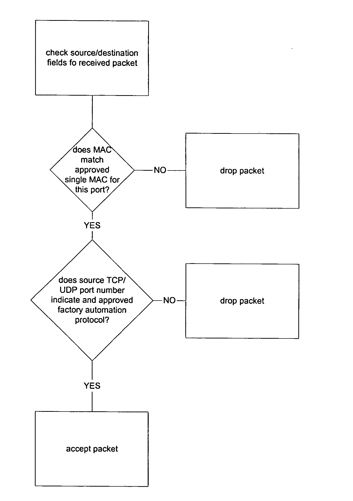
A method and apparatus for providing security to factory automation devices in a switched Ethernet network. Traffic between factory automation devices and an Ethernet switch is limited to packets including approved TCP/UDP port numbers and to selected data rates.

Description

BACKGROUND OF THE INVENTION [0001] Factory automation networks have traditionally utilized proprietary protocols specially designed to facilitate networking of factory automation components, for example, Human-Machine-Interface (HMI) computers, Engineering Workstations, and serial slave devices, at a manufacturing site. Because of their specialized, proprietary nature the costs of these network have remained high. [0002] Recently, interest in using Ethernet in factory automation has grown due the inclusion of inexpensive Ethernet Network Interface Cards (NICs) on most personal computers and the low costs of commercial-off-the shelf components due to commoditization of Ethernet. [0003] In the past, when proprietary manufacturing networks were used on the manufacturing floor no specific security measures were required because security exists due to obscurity. The only NICs available for these proprietary networks are made by specialized equipment vendors such as Rockwell and Honeywell...

Claims


Application Information

Patent Timeline
IPC IPC(8): G06F15/16
CPCH04L63/0236H04L67/12H04L67/322H04L63/101
Inventor COLEY, KENNETHSHUEN, PAULINE
Owner CISCO TECH INC
Why Eureka
Try Eureka