Check patentability & draft patents in minutes with Patsnap Eureka AI!

Helmet face shield

a technology for helmets and shields, applied in the field of helmet shields, can solve the problems of affecting the vision of riders, adding to the manufacturing cost of the face shield assembly, and being difficult to see without a rather bulky perimeter frame, so as to improve the anti-condensation

Inactive Publication Date: 2006-01-19
DOUGLAS THOMAS D A
View PDF19 Cites 48 Cited by
  • Summary
  • Abstract
  • Description
  • Claims
  • Application Information

AI Technical Summary

Benefits of technology

[0009] The present invention permits an inner lens to be engaged to an outer lens such that it is offset therefrom but sealed thereto. The present invention further permits the single pane lens to be converted into a double pane lens having improved anti-condensation properties provided by an air gap trapped between the inner and outer lenses of the sealed double pane lens.

Problems solved by technology

In cold weather, single pane lenses tend to fog up, consequently impairing the rider's vision.
Double pane lens assemblies are significantly thicker than single paned lenses, and their attachment to some helmets which are not specifically designed to accommodate them can accordingly be difficult without the rather bulky perimeter frame.
These face shield perimeter frames can significantly add to the manufacturing cost of the face shield assembly, unduly add bulk and weight to the helmet, and contribute to aerodynamic inefficiencies and increased wind noise.
Most known face shields that do not comprise perimeter frames, and have double pane lenses or have a hydrophilic layer superimposed on a single lens, do not permit removal of one of the lens panes or the anti-condensation layer.

Method used


Image

  • Helmet face shield
  • Helmet face shield
  • Helmet face shield

Examples


Embodiment Construction

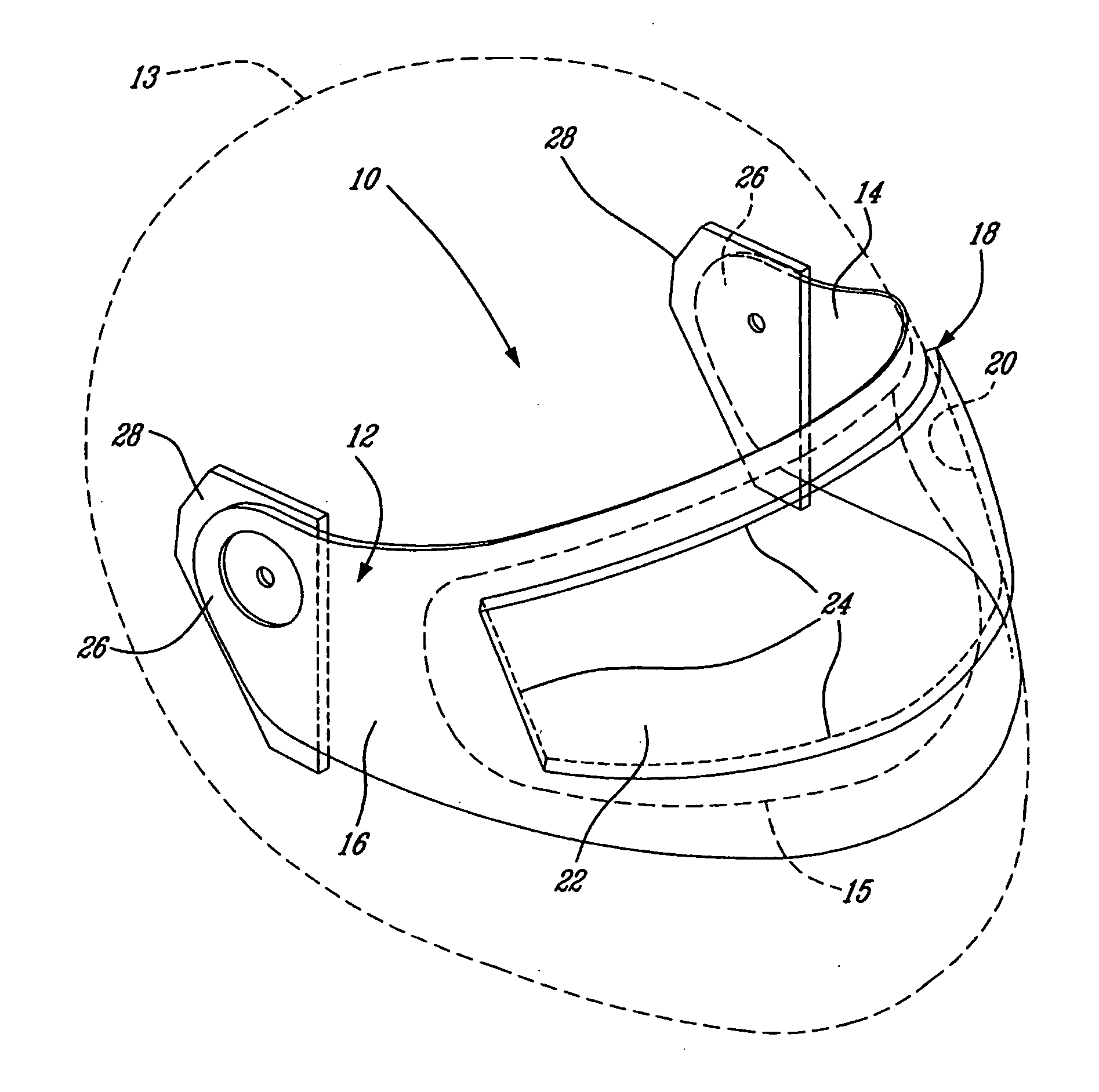
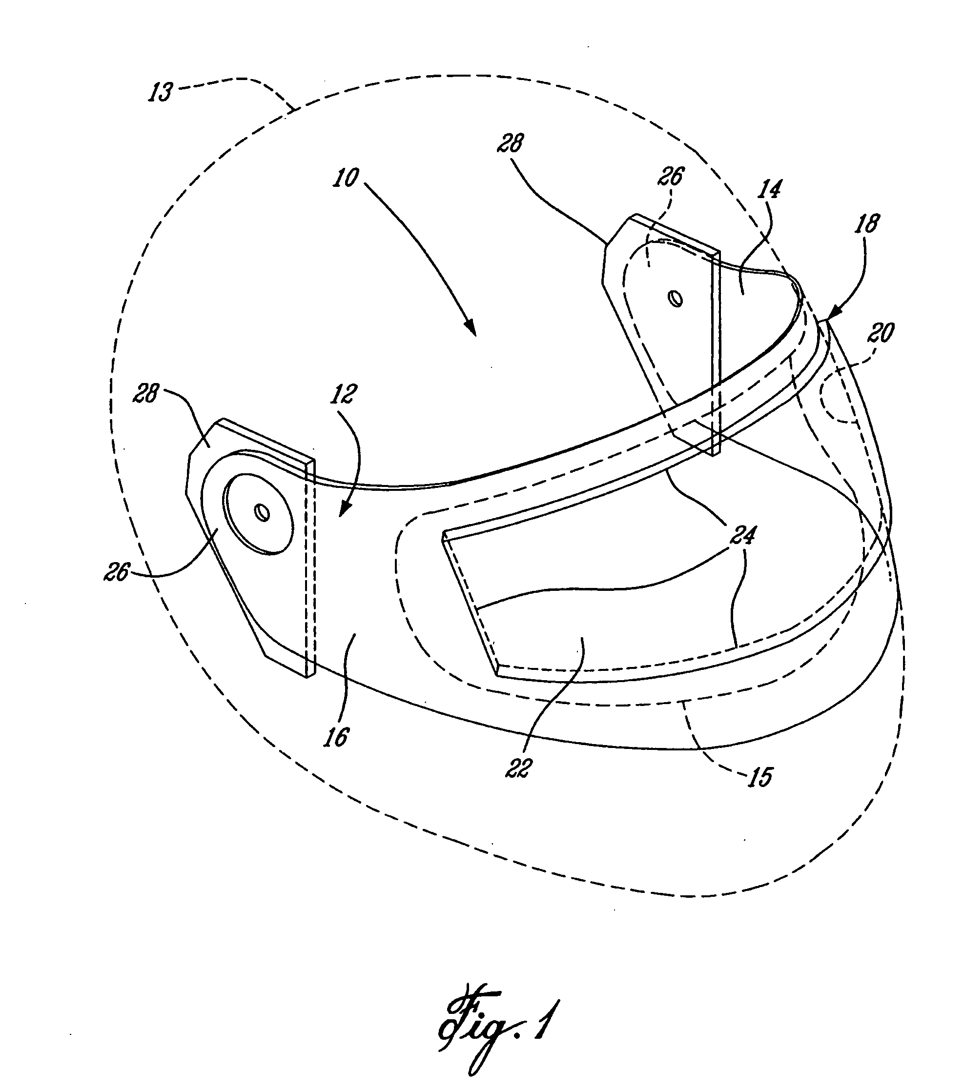
[0018] Referring to FIG. 1, the face shield 10 is adapted to be engaged to, and used with, headgear such as a protective helmet 13 as conventionally used for motorcycle riding, snowmobiling, flying and the like. The face shield 10 is also adapted for use with other protective headgear comprising a transparent face shield, such as paintball masks for example. The face shield 10 comprises primarily a generally transparent main lens 12, thereby providing a single pane lens that does not require a perimeter frame for support or engagement to the protective helmet 13. The main lens 12 is preferably a moulded plastic one-piece element, having a thickness of approximately 2 mm (about 0.07874 inches). The main lens 12 is preferably injection moulded, however other manufacturing techniques could also be used, such as drape or vacuum moulding for example. One skilled in the art will also appreciate that the main lens 12 can have a non-uniform thickness throughout. Particularly, as is known in...


PUM


Abstract

A face shield for headgear comprises a generally transparent main lens, adapted for engagement to the headgear. The main lens comprises a curved inner and outer main lens surfaces and has a central recessed portion with a curved recessed inner lens surface and a curved recessed outer lens surface. The recessed inner lens surface and the recessed outer lens surface are respectively offset from the curved inner and outer main lens surfaces. The recessed portion is adapted to receive a secondary lens such that a sealed air gap is formed between the secondary lens and the main lens, thereby forming a sealed double pane lens having condensation reduction properties.

Description

CROSS-REFERENCE TO RELATED APPLICATIONS [0001] This application is a continuation of U.S. patent application Ser. No. 10 / 769,979, filed on Feb. 3, 2004, and which claims priority on US Provisional Patent Application No. 60 / 444,159, filed on Feb. 3, 2003. The entire contents of both of which are incorporated herein by reference.TECHNICAL FIELD [0002] The present invention relates generally to shields for protective helmets used for snowmobiling, motorcycle riding and the like. More particularly, the present invention relates to a protective face shield having a removable lens portion. BACKGROUND OF THE INVENTION [0003] Protective helmets such as, for example, those used for snowmobiling and motorcycle riding, are well known. They typically include a generally transparent face shield or lens. Two distinct types of helmet face shields are typically employed. Shields having a single pane lens are generally used in warmer environmental conditions. Face shields having a dual lens construc...

Claims


Application Information

Patent Timeline
Patent Type & Authority Applications(United States)
IPC IPC(8): A41D1/06
CPCA42B3/24
Inventor DOUGLAS, THOMAS D. A.
Owner DOUGLAS THOMAS D A
Features
  • R&D
  • Intellectual Property
  • Life Sciences
  • Materials
  • Tech Scout
  • Unparalleled Data Quality
  • Higher Quality Content
  • 60% Fewer Hallucinations
Learn More