Driving unit for washing machine and method for controlling the same

a technology for driving units and washing machines, applied in the field of washing machines, can solve problems such as mechanical, electrical noise, clutches, mechanical and electrical noise increases, and the structure of the driving unit becomes complicated

Active Publication Date: 2006-01-19
LG ELECTRONICS INC
View PDF14 Cites 57 Cited by
  • Summary
  • Abstract
  • Description
  • Claims
  • Application Information

AI Technical Summary

Benefits of technology

[0020] To achieve these objects and other advantages and in accordance with the purpose of the invention, as embodied and broadly described herein, a driving unit for a washing machine includes a bearing housing fixedly secured to an outer tub of the washing machine, a motor mounted on the bearing housing, a ring gear shaft rotatably mounted to the bearing housing, the ring gear shaft being coupled to an inner tub of the washing machine, a carrier shaft rotatably mounted to the ring g...

Problems solved by technology

However, conventional driving units of the washing machine have several problems.
First, if the driving unit has the induction motor applied thereto, even though a unit cost of the motor can be lowered, there has been a problem in that a structure of the driving unit becomes complicated because a clutch and a speed reduction device are required additionally for regulating a rotation speed of the motor.
Second, since the driving unit moves together with devices, such as clut...

Method used


Image

  • Driving unit for washing machine and method for controlling the same
  • Driving unit for washing machine and method for controlling the same
  • Driving unit for washing machine and method for controlling the same

Examples


first embodiment

[0063] the one directional holding device will be described.

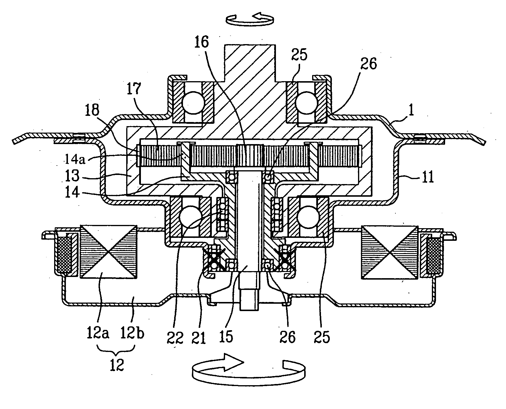
[0064] Referring to FIG. 1, the first embodiment of the one directional holding device includes a first one way bearing 21 between the bearing housing 11 and the carrier shaft 14 for making the carrier shaft to be held at the bearing housing 11 only when the driving shaft 15 is rotated in one direction, and a second one way bearing 22 between the ring gear shaft 13 and the carrier shaft 14 for holding the ring gear shaft 13 and the carrier shaft only when the driving shaft 15 is rotated in the other direction.

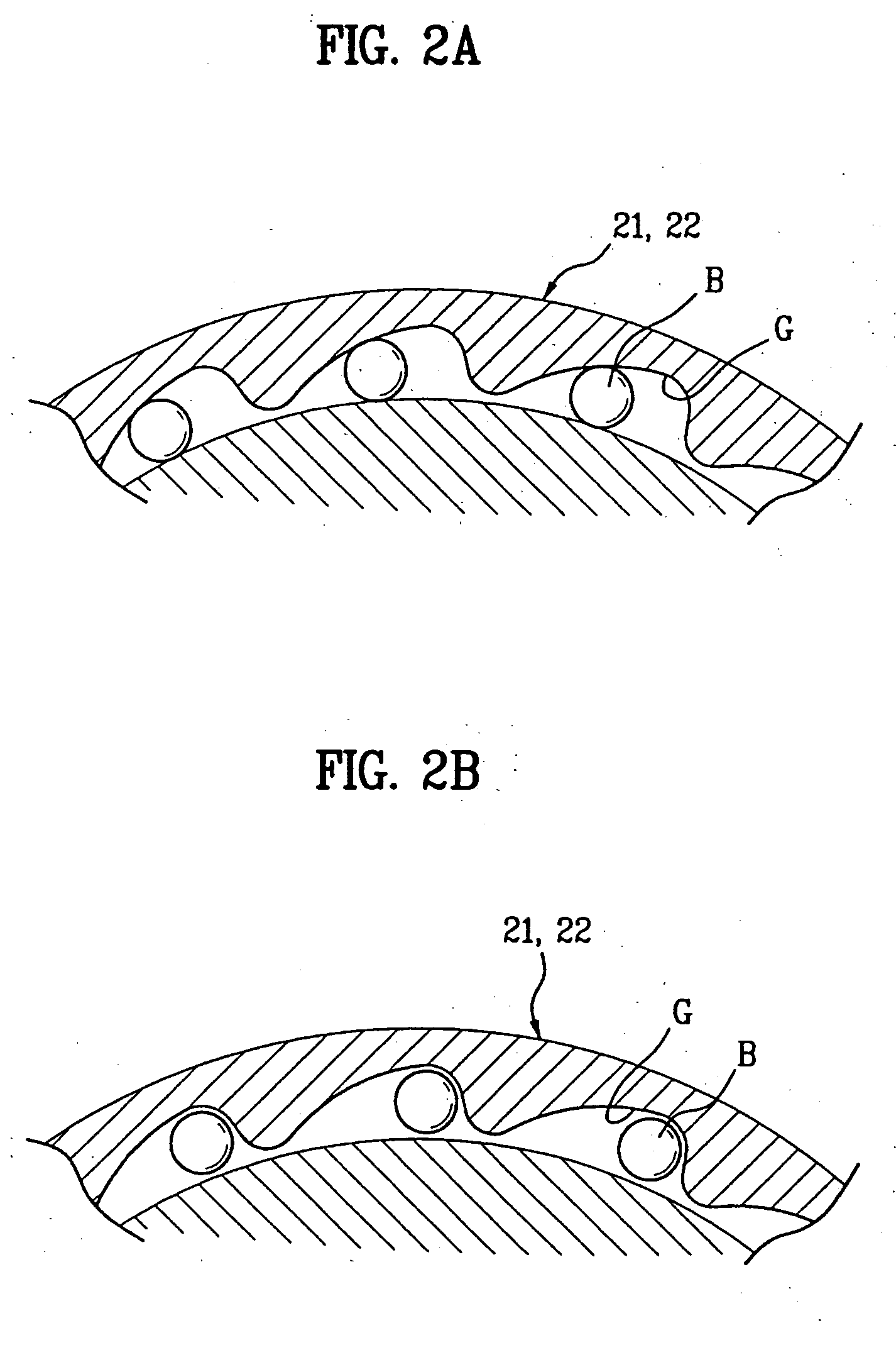
[0065] Referring to FIGS. 2A and 2B, the first, and second one way bearings 21, and 22 each has a plurality of grooves G along an inside circumferential surface of a bearing race, in each of which a ball B is rotatably placed. The groove has one side with a large curvature, and the other side with a small curvature.

[0066] Therefore, as shown in FIG. 2A, if a shaft rotates in one direction, the ball B moves in a direc...

second embodiment

[0092]FIG. 5 illustrates a diagram of the one directional holding device of the driving unit in FIG. 1. FIGS. 6A, and 6B illustrate diagrams of operation states of a driving unit when the washing machine in FIG. 5 is operated in a washing mode. FIGS. 7A, and 7B illustrate diagrams of operation states of a driving unit when the washing machine in FIG. 5 is operated in a spinning mode.

[0093] Referring to FIG. 5, the one directional holding device includes a first one way bearing 31 between the bearing housing 11 and the carrier shaft 14 for making the carrier shaft 14 to be held at the bearing housing 11 only when the driving shaft 15 is rotated in one direction, and a second one way bearing 32 between the carrier shaft 14 and the driving shaft 15 for holding the carrier shaft 14 and the driving shaft 15 only when the driving shaft 15 is rotated in the other direction.

[0094] On outside circumferential surfaces of the ring gear shaft 13, there are supporting bearings 35 mounted thereo...

third embodiment

[0114] The operation of the driving unit having the one directional holding device applied thereto will be described. At first, referring to FIGS. 9A and 9B, the operation of the driving unit will be described when the washing machine is in a washing mode.

[0115] Referring to FIG. 9A, when power is applied to the motor 12 following starting of the washing cycle, the driving shaft 15 is rotated in one direction (i.e., a clockwise direction) (ωinput), following rotation of the rotor 12b in one direction.

[0116] In this instance, the carrier shaft 14 is held at the bearing housing 11 by the first one way bearing 41 (ωcarrier).

[0117] In the meantime, since the second one way bearing 42 is mounted such that a holding direction of the second one way bearing 42 is opposite to the holding direction of the first one way bearing 41, the driving shaft 15 is not held at the carrier shaft 14.

[0118] Under this state, the planet gears 17 engaged with the sun gear 16 rotate in a direction (i.e., c...


PUM


Abstract

A driving unit for a washing machine, and method for controlling the same. The driving unit includes a bearing housing fixedly secured to an outer tub. A motor is mounted on the bearing housing. A ring gear shaft is rotatably mounted to the bearing housing and is coupled to an inner tub. A carrier shaft is rotatably mounted in the ring gear shaft, with a driving shaft rotatably mounted in the carrier shaft. The driving shaft is coupled to the motor. A reduction gear is positioned between the ring gear shaft and the carrier shaft to reduce a speed of the ring gear shaft. A one directional holding device that holds the carrier shaft when the driving shaft rotates in a first direction, and holds two of the carrier shaft, the ring gear shaft, and the driving shaft when the driving shaft rotates in a second direction.

Description

CROSS-REFERENCE TO RELATED APPLICATIONS [0001] This application claims the benefit of Korean Application Nos. 10-2004-0055444 and 10-2004-0055445, both filed on Jul. 16, 2004, which are hereby incorporated by reference in their entireties. BACKGROUND OF THE INVENTION [0002] 1. Field of the Invention [0003] The present invention relates to washing machines, and more particularly, to a washing machine which enables simplification of a structure of a driving unit and which provides an adequate driving torque even if a small sized motor is utilized therein, and a method for controlling the same. [0004] 2. Discussion of the Related Art [0005] In general, washing machines wash laundry by action of circulation of washing water, and a chemical action, such as detergent, and the like. [0006] In the washing machines, there are top load type washing machines, and front load type washing machines. In the top load type washing machines, there are tub rotating type machines, and pulsator type was...

Claims


Application Information

Patent Timeline
IPC IPC(8): D06F33/00D06F35/00
CPCD06F37/40D06F37/36
Inventor KIM, DONG WONWOO, KI CHUL
Owner LG ELECTRONICS INC
Why Eureka
Try Eureka