
Mitre saw with adjustable fence

Inactive Publication Date: 2006-01-19
BLACK & DECKER INC
View PDF19 Cites 8 Cited by
  • Summary
  • Abstract
  • Description
  • Claims
  • Application Information

AI Technical Summary

Benefits of technology

[0017] In addition, the present invention may also provide for a miter saw which allows the fence to be longitudinally adjusted along the cutting line so as to vary the operative cutting depth provided by such miter saws. This feature is particularly beneficial for use with compound sliding miter saws for cutting objects having varied thicknesses and depth.
[0021] Preferably, the work surface will comprise at least one guide track and the fence will comprise at least one track following member in co-operative sliding engagement therewith, which facilitates the angular adjustment of the fence about the cutting line. In one embodiment, the track itself may be linear whereby it is therefore preferable that the or the at least one track following member is longitudinally adjustable along the elongate fence as the fence is pivoted about the pivot axis. Alternatively, or in combination, the work surface may in fact comprise at least two tracks and the fence comprise at least two track following members for co-operating engagement therewith. Again one or both of the track following members may be longitudinally adjustable about this elongate fence and the fence may optionally utilise a fixed pivot axis or may be simply inclined between the two tracks themselves relative to the cutting line.

Problems solved by technology

However, while this type of conventional miter saw provides for an efficient manner of adjusting the miter angle, the mechanisms employed to provide for such a rotatable table releasably secured to a base assembly are somewhat complex and expensive to manufacture and service.

Method used


Image

  • Mitre saw with adjustable fence
  • Mitre saw with adjustable fence
  • Mitre saw with adjustable fence

Examples


Embodiment Construction

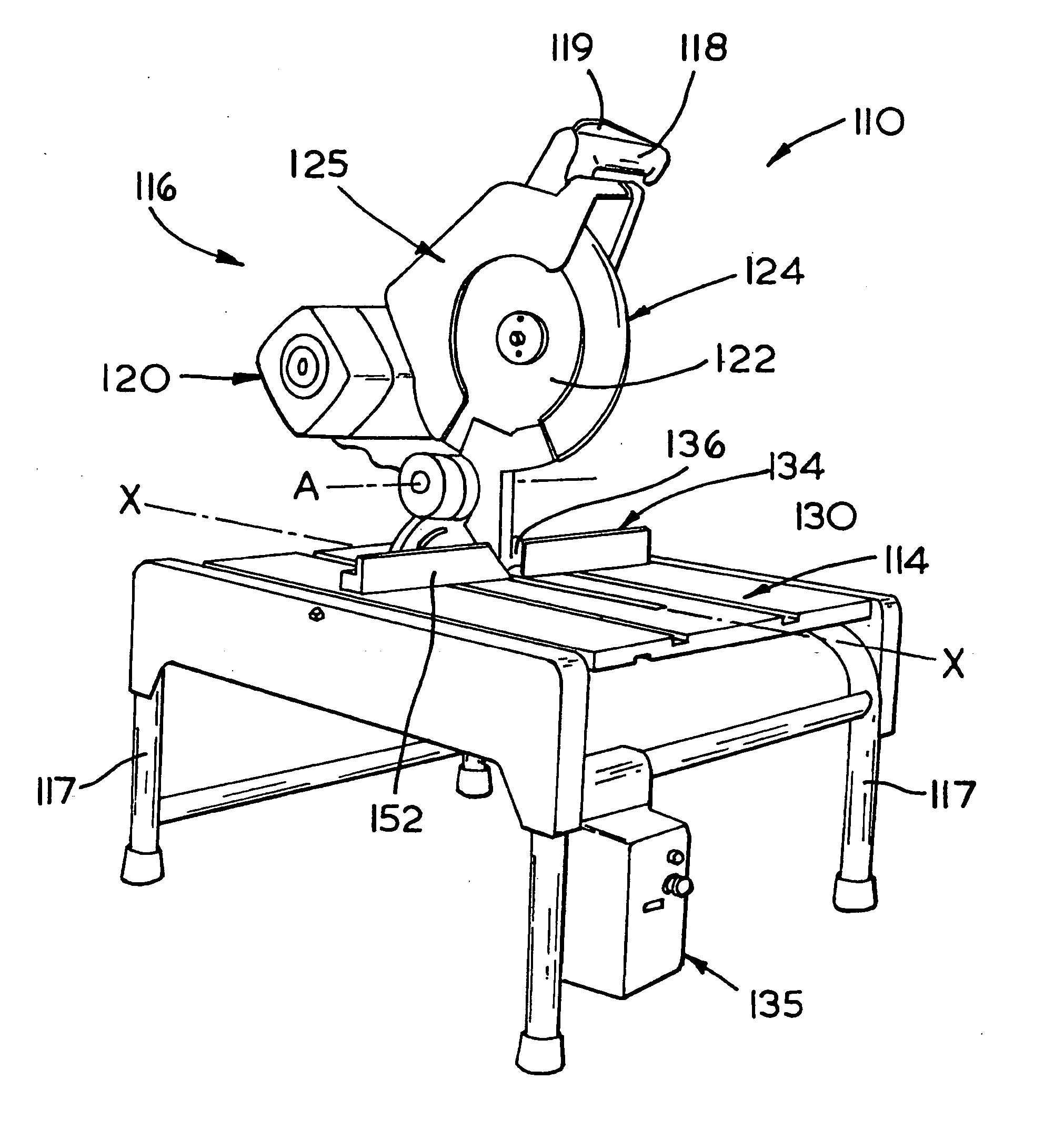
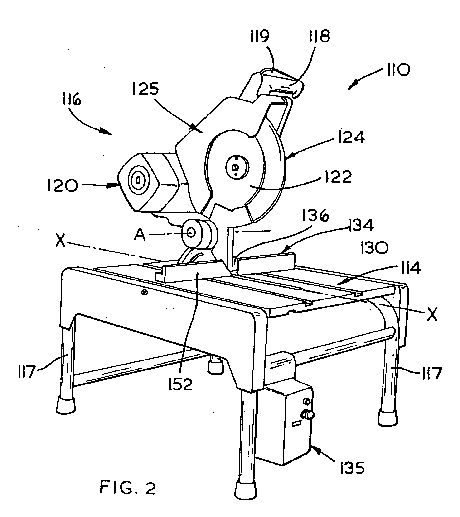
[0032] Referring now to FIG. 2, showing the present invention, the table miter saw 110 preferably has a saw assembly 116 comprising a motor housing 112 which is connected through a bearing assembly (not shown) to a circular saw blade 122. The saw assembly 116 may have a handle 118 with a trigger switch 119. Handle 118 may be mounted to motor housing 112. Blade 122 may be mounted within a blade housing 125 and surrounded by a displaceable blade guard 124.

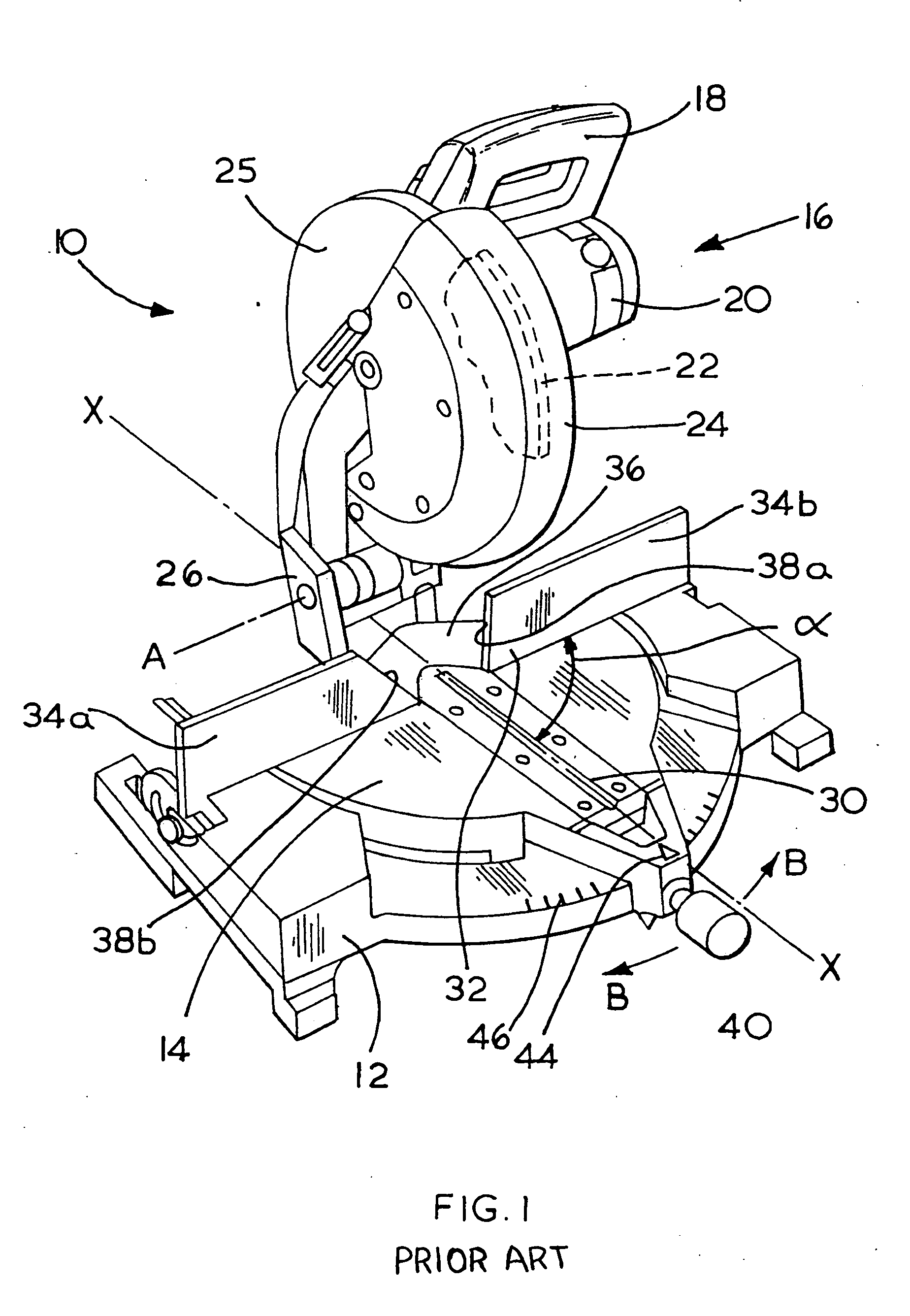
[0033] Saw assembly 116 may be mounted on a table or working surface 114. Work surface 114 may be securely mounted on four sturdy legs 117 to provide a stationary miter saw. Persons skilled in the art will recognize that, while the work surface 114 is shown as mounted on legs 117, the current invention is equally applicable to a portable miter saw of the type shown in FIG. 1. Saw assembly 116 is preferably pivotally mounted about an axis A through a conventional hinge arrangement so as to allow pivotal displacement of the saw blade ...


PUM

PropertyMeasurementUnit
Timeaaaaaaaaaa
Angleaaaaaaaaaa
Stiffnessaaaaaaaaaa

Abstract

A miter saw 110 having an operable cutting blade 122 pivotally supported relative to a working surface 114 and displaceable in a first cutting plane which intersects the work surface 114 along a first cutting line X-X. The miter saw has an adjustable elongated fence 134 angularly displaceable relative to the first cutting line X-X. The fence 134 is adjustably mounted on and supported by the working surface 114.

Description

FIELD OF THE INVENTION [0001] The present invention is directed to miter saws and more particularly to power driven miter saws where the angle between the cutting blade and the support fence is adjustable to provide for a wide range of cutting angles. BACKGROUND OF THE INVENTION [0002] Power driven miter saws of this type are well known and commonly used on building sites and by those involved in woodworking to allow for ease of cutting various lengths of wood to have required simple or complex (compound) cut angles. The basic type of miter saw simply comprises a circular saw blade which is operable in a cutting plane substantially perpendicular to a work surface on which the workpiece to be cut is supported by an appropriate fence. The plane in which the blade is operable can then be angularly adjusted relative to the fence (which is fixed relative to the base of the miter saw) to change the cutting angle relative thereto. [0003] Alternatively, such miter saws may additionally furt...

Claims


Application Information

Patent Timeline
IPC IPC(8): B23D19/00B27B27/08B27G5/02
CPCB27G5/023B27B27/08Y10T83/7697Y10T83/7726Y10T83/8773
Inventor ROSSETTI, MIRCOBETTACCHINI, MARCELLO
Owner BLACK & DECKER INC
Learn More