Vehicle fueling arrangement

a fuel arrangement and vehicle technology, applied in the direction of electric control, machines/engines, ignition safety means, etc., can solve the problems of leaving the engine running, and achieve the effects of limiting and disabling the operation of the vehicle engin

Inactive Publication Date: 2006-01-19
GM GLOBAL TECH OPERATIONS LLC
View PDF2 Cites 24 Cited by
  • Summary
  • Abstract
  • Description
  • Claims
  • Application Information

AI Technical Summary

Problems solved by technology

However, many fueling stations are now self-service and customers often leave their engines running, especially in cold weather.

Method used


Image

  • Vehicle fueling arrangement
  • Vehicle fueling arrangement
  • Vehicle fueling arrangement

Examples


Embodiment Construction

[0012] The following detailed description is merely exemplary in nature and is not intended to limit the invention or the application and uses of the invention. Furthermore, there is no intention to be bound by any expressed or implied theory presented in the preceding technical field, background, brief summary or the following detailed description.

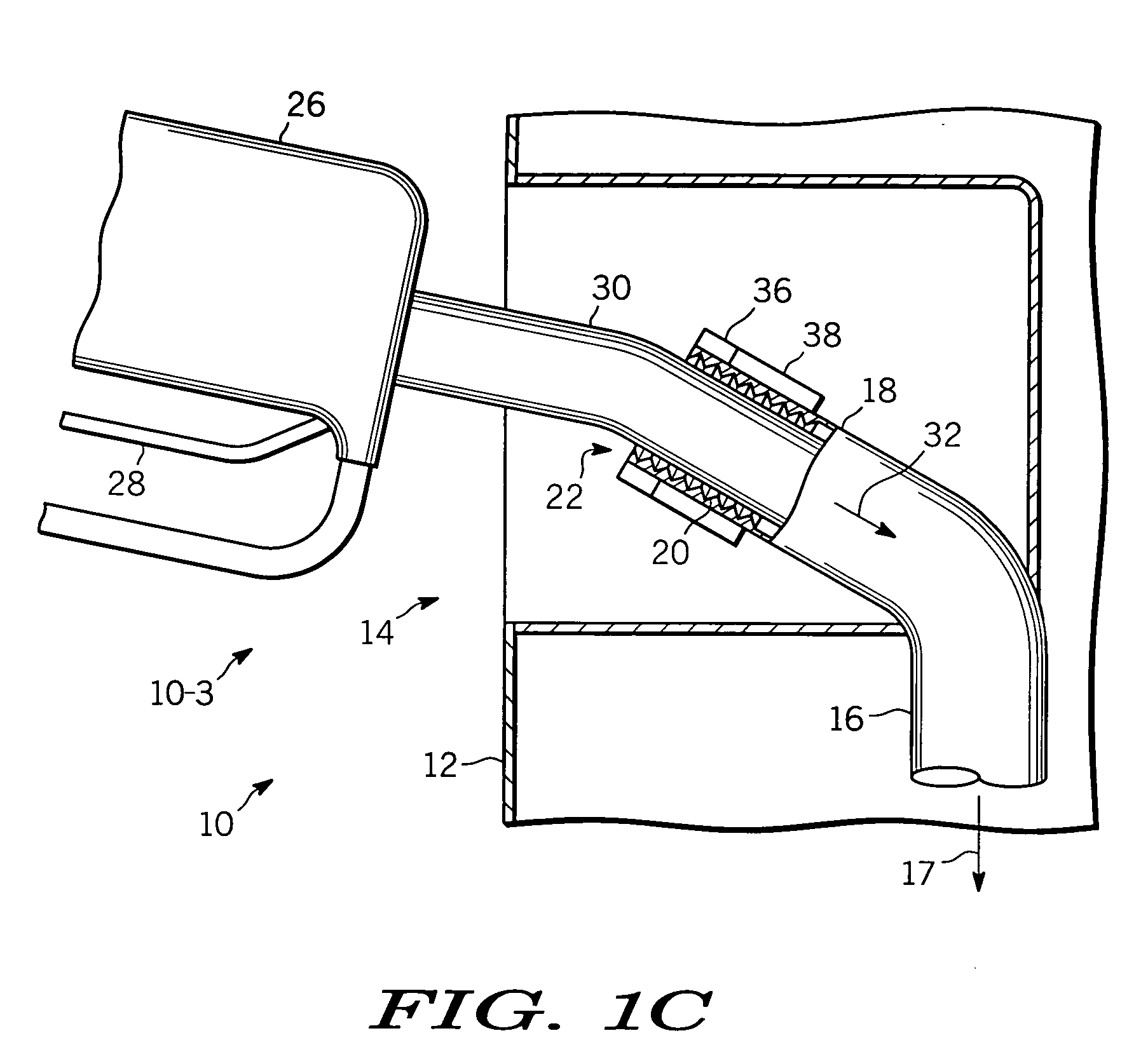
[0013]FIGS. 1A-1C are simplified partially cut-away and cross-sectional views of fuel fill-pipe region 10 of a vehicle according to the present invention for three fueling situations 10-1, 10-2, 10-3. Fuel fill-pipe region 10 comprises vehicle body portion 12 having optionally recessed fill-pipe access region 14. Fuel fill-pipe 16 has end region 18 that protrudes into optional access region 14. While fill-pipe access region 14 is desirably recessed to protect end region 18 of fill-pipe 16 from knocks and bumps, this is not essential and end region 18 of fill-pipe 16 may protrude directly from vehicle body 12 without recess 14. End region...


PUM


Abstract

Methods and apparatus are provided for limiting engine operation during fueling. The apparatus comprises, an engine control for enabling or disabling operation of the engine, one or more sensors for detecting whether (i) a cap is on the vehicle fuel fill-pipe, and (ii) a fueling nozzle is in the fuel fill-pipe, a processor coupled to the engine control and the one or more sensors receiving information therefrom and directing the engine control to enable or disable the vehicle engine depending upon the sensor outputs, thereby, disabling the engine when the cap is not on the fill-pipe and / or a fueling nozzle is in the fill-pipe, and enabling the engine when not true. In a further embodiment, a fuel level sensor coupled to the processor is used to detect whether a fuel level change rate R(t)≧Rc where Rc is a predetermined value, and if so, disabling the engine.

Description

TECHNICAL FIELD [0001] The present invention generally relates to vehicle fueling safety, and more particularly relates to inhibiting engine operation during fueling. BACKGROUND [0002] Most vehicle fueling stations request that engines be turned off during fueling to avoid a risk of fire or explosion due to engine operation igniting fuel vapors associated with the fueling process. This is particularly important when fueling with gasoline. This is a voluntary process that depends upon user cooperation or perhaps station attendant enforcement. However, many fueling stations are now self-service and customers often leave their engines running, especially in cold weather. Thus, there is a need for a system that would insure that engines are automatically disabled during fueling. [0003] Accordingly, it is desirable to provide an apparatus and method that disables the engine when fueling or when fueling is about to take place. In addition, it is desirable that the apparatus and method be ...

Claims


Application Information

Patent Timeline
Patent Type & Authority Applications(United States)
IPC IPC(8): F02B77/08
CPCF02D41/042F02D41/021
Inventor KROPINSKI, MICHAEL A.BOLANDER, THOMAS E.MAKRIS, ALEXANDER N.BAUERLE, PAUL A.
Owner GM GLOBAL TECH OPERATIONS LLC
Why Eureka
Try Eureka