Ceramic heater, glow plug, and ceramic heater manufacturing method

Active Publication Date: 2006-01-19
NGK SPARK PLUG CO LTD
View PDF9 Cites 36 Cited by
  • Summary
  • Abstract
  • Description
  • Claims
  • Application Information

AI Technical Summary

Benefits of technology

[0013] It is therefore an object of the invention to provide

Problems solved by technology

The inventors also found that degradation of the electrode part is

Method used


Image

  • Ceramic heater, glow plug, and ceramic heater manufacturing method
  • Ceramic heater, glow plug, and ceramic heater manufacturing method
  • Ceramic heater, glow plug, and ceramic heater manufacturing method

Examples


Example

[0092] Test Examples 1 and 2 embodying the invention will now be discussed with reference to the accompanying drawings. However, the present invention should not be construed as being limited thereto. Test Example 1 includes Examples 1-1 to 1-3 and Comparative Examples 1-1 and 1-2. Test Example 2 includes Examples 2-1 to 2-8 and Comparative Examples 2-1 to 2-9.

TEST EXAMPLE 1

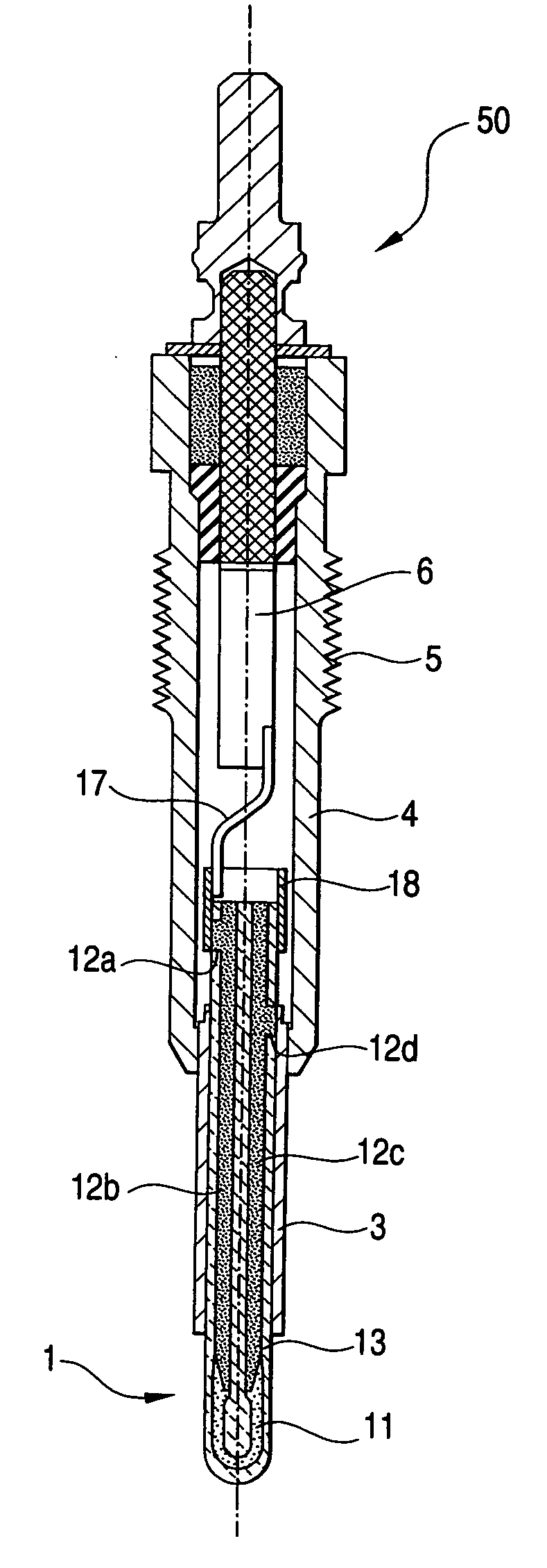
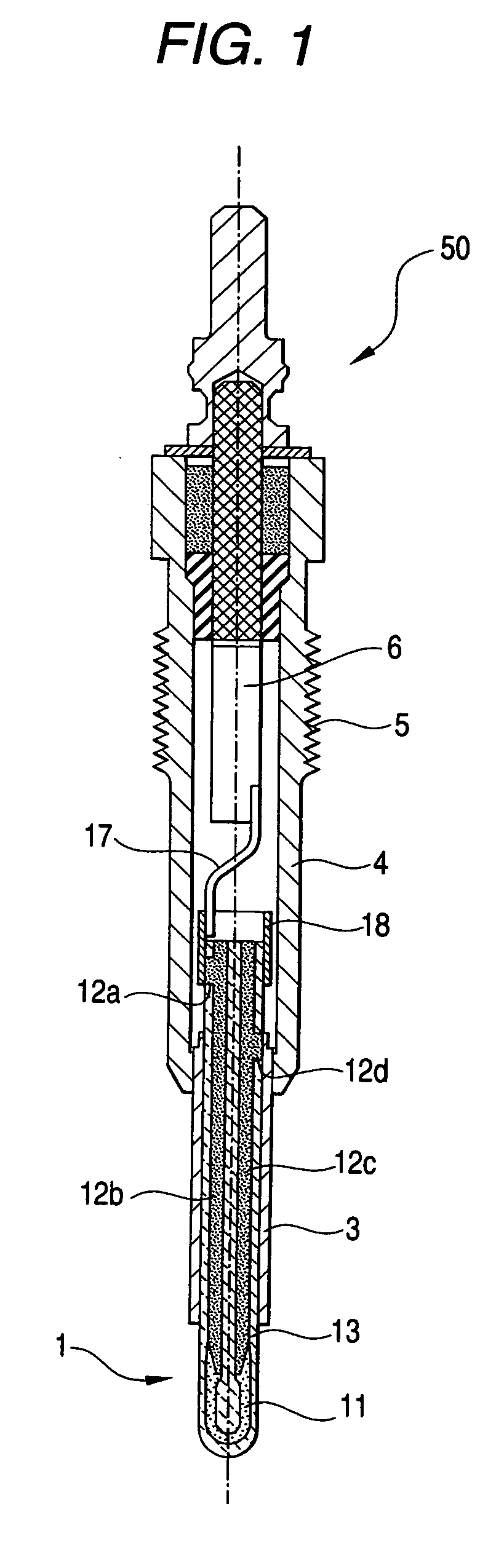
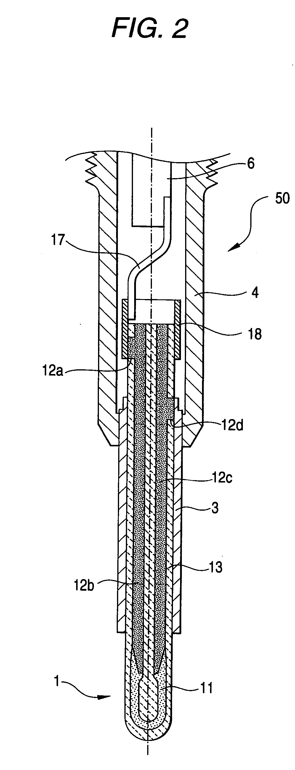
[0093] Test Example 1 was carried out to determine durability of a ceramic heater over long term use. First, a glow plug 50 employing a ceramic heater 1 of Examples 1-1 to 1-3 and Comparative Examples 1-1 and 1-2 as shown in FIGS. 1 and 2 will be discussed. The glow plug 50 includes a cylindrical metal shell 4, a columnar ceramic heater 1 provided inside the tip end side of the metal shell 4 through a metal cylinder 3 and having a heating part at its tip end, a center pole 6 provided in the rear end side of the metal shell 4, and a connection fitment 17 and a metal ring 18 for connecting the center pole 6 and t...

Example

[0125] Test Example 2 is an evaluation for determining whether the ceramic heater 1 has sufficient break-resistant strength and whether breakage, etc., during manufacturing or installation, etc., can be suppressed as the material of the electrode parts 12a, 12d for the ceramic heater 1 of Test Example 1 is changed. The lead parts 12b and 12c are made of the same material as the electrode parts 12a and 12d. Test Example 2 includes Examples 2-1 to 2-8 and Comparative Examples 2-1 to 2-9.

[0126] In the ceramic heaters 1 of Examples 2-1 to 2-8 and Comparative Examples 2-1 to 2-9, the compounding ratio between the insulating material and WC of the electrode parts 12a and 12d and the content of SiO2 and Er2O3 in the insulating material was changed as indicated in Table 4. The structure and manufacturing method of the ceramic heater 1, the structure of the glow plug 50 manufactured using the ceramic heater 1, and the like are as described in Test Example 1 and therefore will not be repeate...


PUM


Abstract

A ceramic heater which includes: a cylindrical substrate including an insulator; a resistor provided in one end side of the substrate; a pair of lead parts provided in the substrate, connected to the resistor and extending to an opposite end side of the substrate; and a pair of electrode parts exposed to a surface at an opposite end side of the substrate and connected respectively to the lead parts. Both lead parts are made of the same material as both electrode parts. An axial cross-sectional area of the electrode part is equal to or larger than a cross-sectional area of the lead part in a direction perpendicular to an axis of the ceramic heater.

Description

BACKGROUND OF THE INVENTION [0001] 1. Field of the Invention [0002] This invention relates to a ceramic heater, a glow plug, and a ceramic heater manufacturing method. [0003] 2. Description of the Related Art [0004] JP-A-2003-56848 discloses a glow plug including a cylindrical metal shell, a columnar ceramic heater provided inside the tip end side of the metal shell and having a heating part at its tip end, and a center pole provided in the rear end side of the metal shell. [0005] The ceramic heater of JP-A-2003-56848 has a cylindrical substrate made of a silicon nitride insulating material, a resistor buried in one end side of the substrate, a pair of lead parts buried in the substrate, the lead parts being connected to the resistor and extending to an opposite end side of the substrate, and electrode parts exposed at the opposite end surface of the substrate and connected to the lead parts. The ceramic heater of JP-A-2003-56848 has a metal cylinder and a metal ring on its outer pe...

Claims


Application Information

Patent Timeline
IPC IPC(8): F23Q7/22F02N99/00
CPCF23Q7/00F23Q7/001H05B2203/027H05B3/141F23Q2007/004
Inventor KONISHI, MASAHIROSATO, HARUHIKOSUZUKI, TETSUYAMATSUI, TAKAHIRO
Owner NGK SPARK PLUG CO LTD
Why Eureka
Try Eureka