

Liquid crystal display, driver chip and driving method thereof
a technology of liquid crystal display and driver chip, which is applied in the direction of instruments, computing, electric digital data processing, etc., can solve the problems of increasing the number of driver chips required, severe attenuation of pixel signals, and increasing the severity of signal attenuation problems, so as to increase the transmitting clock rate
- Summary
- Abstract
- Description
- Claims
- Application Information
AI Technical Summary
Benefits of technology
Problems solved by technology
Method used
Image

Examples
Embodiment Construction
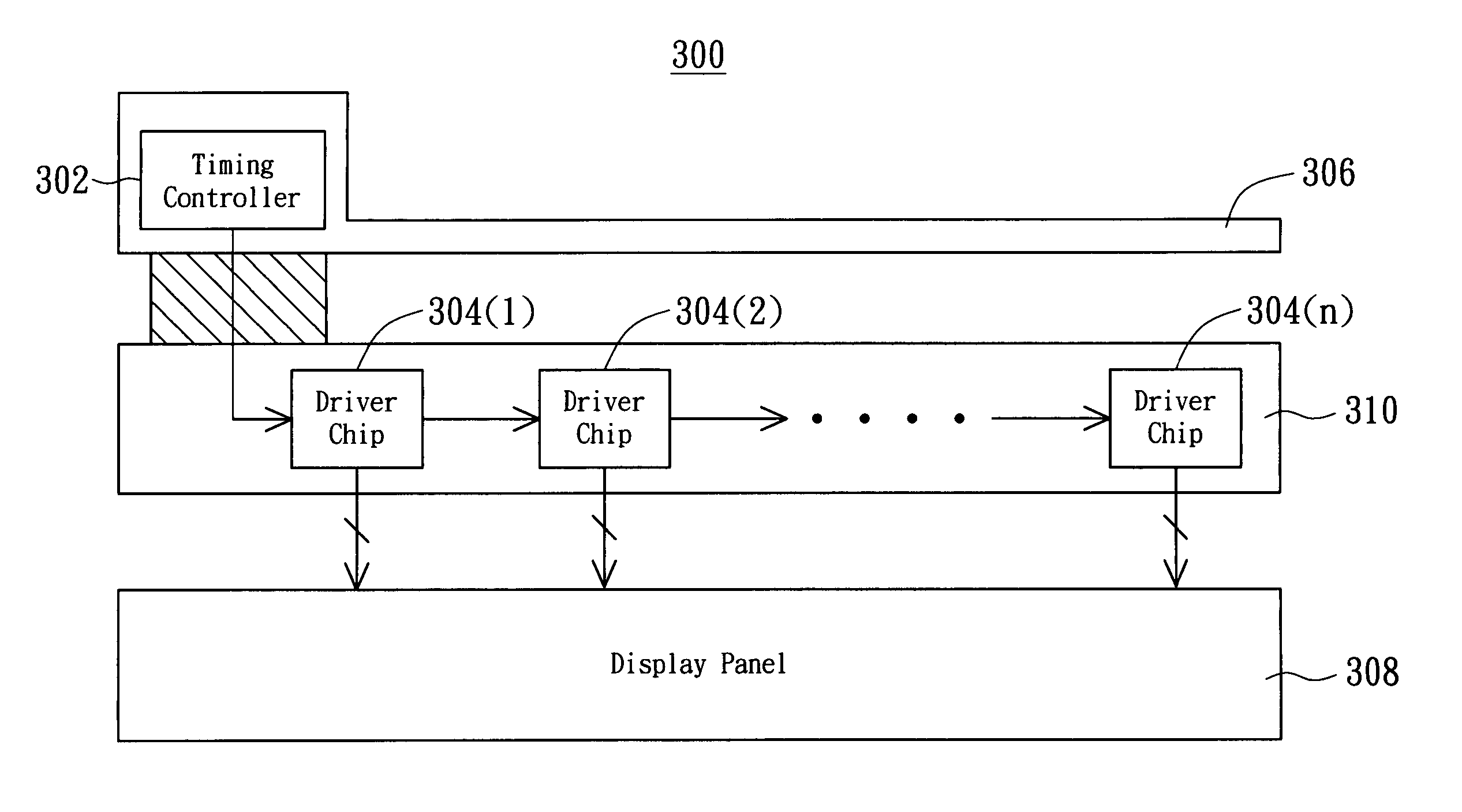
[0016]FIG. 3 shows illustration of a driver circuit of a LCD according to a preferred embodiment of the invention. LCD 300 includes a timing controller 302, n driver chips 304 that are cascaded together, a Print Circuit Board (PCB) 306, and a glass substrate 310. Timing controller 302 disposed on PCB 306 outputs a pixel signal, such as in a differential type. First driver chip 304(1) is electrically connected to timing controller 302. Driver chip 304(1), 304(2), 304(3) . . . 304(n) are serially connected. Driver chip 304(1) disposed on glass substrate 310 receives the pixel signal output from timing controller 302, and then sends the pixel signal to next driver chip 304(2), and driver chip 304(2) in turn sends the pixel signal to next driver chip 304(3), and the pixel data continues to be transmitted in this fashion until reaching the last driver chip 304(n). The pixel signal is being transmitted between the driver chip 304 in differential mode, or in alternation between differentia...
PUM
| Property | Measurement | Unit |
|---|---|---|
| impedances | aaaaa | aaaaa |
| power consumption | aaaaa | aaaaa |
Abstract
Description
Claims
Application Information