Orthodontic bracket system

a bracket system and orthodontic technology, applied in the field of applications, can solve the problems of increasing the risk of infection, irritating cheek and gum tissue, and ligatures can suffer from force decay and staining, and achieve good control over the movement of the appliance and the associated tooth

Active Publication Date: 2006-01-19
ORTHODONTIC DESIGN SOLUTIONS L L C
View PDF25 Cites 66 Cited by
  • Summary
  • Abstract
  • Description
  • Claims
  • Application Information

AI Technical Summary

Benefits of technology

[0022] According to the invention in a general aspect, an orthodontic appliance comprises a base for bonding the appliance to a tooth; a body extending from the base; an archwire slot extending across the body in a generally mesial-distal direction and opening in a generally occlusal-gingival direction; and a resiliently deformable retention device associated with the slot to permit both entry and removal of an archwire from the slot. Because the slot opens in a generally occlusal-gingival direction, the buccal and lingual sides of the archwire slot in this invention are immovable relative to each other, and thereby provide good control over movement of the appliance and the associated tooth whenever torquing, tipping, intruding or extruding of the tooth is desired. The archwire is releasably retained by the retention device in the archwire slot without requiring manual ligation using O-rings, stainless steel ligatures and the like.
[0023] Preferably, the retention device comprises a spring for exerting force on a retained archwire having a predetermined minimum dimension against both a lingual and a gingival wall of the archwire slot. The spring is beneficial for providing efficient transmission of force, particularly torque, from an archwire to the tooth via the orthodontic appliance. Retained archwires having less than the predetermined minimum dimension are relatively free to slide within the slot for the initial leveling and aligning phases of treatment.
[0024] Still more preferably, the archwire slot is dimensioned to receive and fully seat a ribbon archwire. The ribbon archwire, having an elongated cross-section in a generally occlusal-gingival direction (rectangle or oval, for instance), provides superior torque control when compared with rectangular cross-section wires oriented parallel to the occlusal plane, as used with edgewise slot systems. As such, three-dimensional control of tooth movement is facilitated.

Problems solved by technology

Elastomeric ligatures can suffer from force decay and staining, while metal ligatures often have sharp ends that may retain food, irritate cheek and gum tissue, and increase the risk of infection caused by puncture of an operators tissue through a glove-covered hand.
However, known self-ligating orthodontic brackets are not entirely satisfactory because optimal control over torquing movement as described above is often difficult to achieve.
Another problem that has been noted in connection with conventional direct-bonded appliances, including self-ligating brackets, is the possibility that such brackets may spontaneously debond from the patient's tooth when the teeth are severely maloccluded.
In such instances, the inherent tendency of the archwire to return to its normal arch-shaped configuration may cause the archwire to exert a substantial force and / or torque on the appliance bonded to the severely maloccluded tooth.
Unfortunately, the bracket may then debond from the tooth if the archwire exerts a force that is larger than the force required to debond the bracket.
Most clip and hinge devices currently commercially available have proven to be difficult to open in the posterior region of the mouth.
This is due to the limited working space available between the patients' cheeks and the buccally-oriented entrance of archwire slot.
A particular disadvantage of the edgewise bracket self-ligating systems such as those described above is that they lack in truly efficient torque control.
As a result, prior art self-ligating appliances generally only achieve full-seating and thereby truly efficient torque expression through additional adjustments made to the archwire by the clinician.
However, the configurations shown are limited to edgewise (i.e., horizontal) bracket systems.
They are further limited, by their configuration, to require selection of smaller-diameter wires throughout the entire system, as a larger diameter wire would not be held effectively by the shutter in the case of a severe malocclusion.
Furthermore, control and expression of forces, particularly torque, is limited because the configurations only express torque efficiently when a full-sized finishing archwire is in place.

Method used


Image

  • Orthodontic bracket system
  • Orthodontic bracket system
  • Orthodontic bracket system

Examples


Embodiment Construction

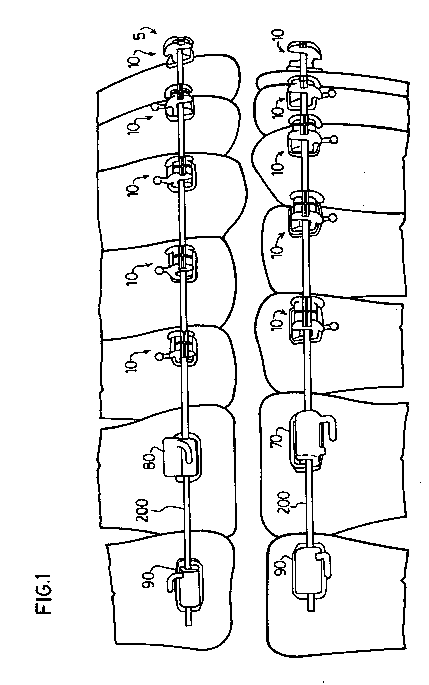
[0068] Referring to the drawings, FIG. 1 is a side elevational view of a ribbon arch self-ligating bracket system 5 provided in accordance with one embodiment of the present invention. System 5 is comprised of brackets for anterior and posterior teeth on both the upper and lower arch, linked with a ribbon archwire.

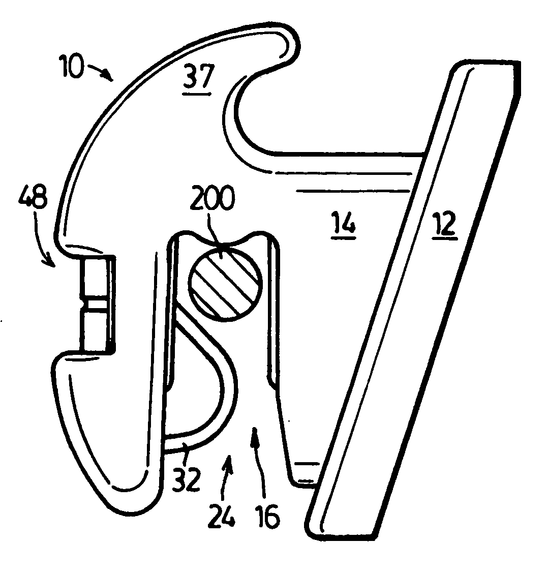
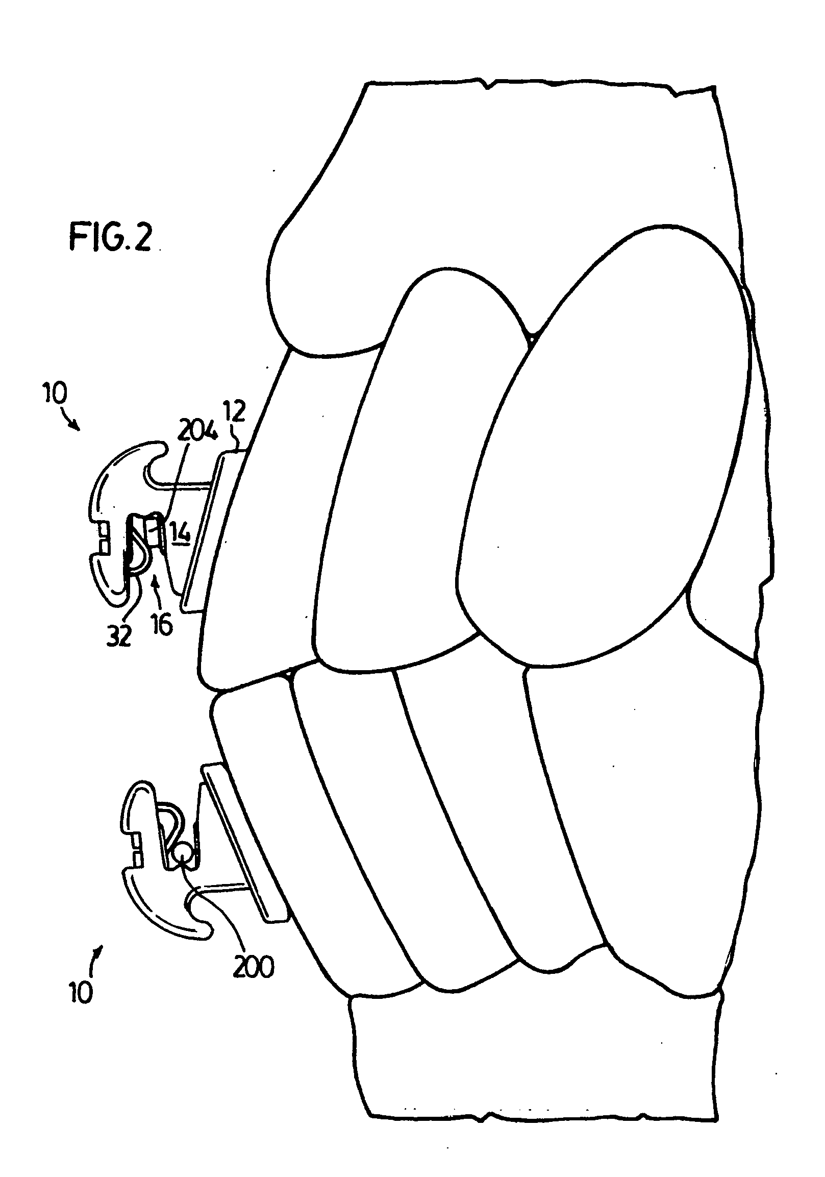
[0069]FIG. 2 is an enlarged partial side-elevational view of the bracket system of FIG. 1 showing brackets 10 on the upper and lower incisor. FIGS. 3 to 9 show bracket 10 from various angles, both with and without inserted archwires.

[0070] Bracket 10 comprises a base 12 and a body 14 extending from the base 12 in a buccal / labial direction. Base 12 is adapted to face and be bonded to a patient's tooth in a known manner, such as a mesh bonding pad, or an integral base.

[0071] An archwire slot 16 extends across body 14 in a generally mesial-distal direction. Archwire slot 16 is bounded on three sides by a buccal / labial wall 18, a lingual wall 20, and a gingival wall 22. Arc...


PUM


Abstract

A novel orthodontic bracket system comprised of orthodontic appliances, such as brackets or buccal tubes, with a vertical instead of conventional horizontal slot orientation. The occlusal-gingival slot orientation minimizes the risk of unintentional debonding of the bracket as a result of insertion and removal of the archwire. An archwire retention mechanism designed to guide, retain and / or seat the archwire. The archwire retention mechanism releases the archwire from the archwire slot whenever appropriate force is applied, or manipulation of physical properties of the material are altered by the operator.

Description

REFERENCE TO RELATED APPLICATION [0001] This application claims priority under 35 U.S.C. 119(e) from U.S. Provisional Patent Application No. 60 / 588,399 filed Jul. 16, 2004.FIELD OF THE INVENTION [0002] This invention broadly relates to an appliance primarily but not exclusively used in orthodontic treatment. More particularly, the present invention relates to an orthodontic appliance, such as a bracket or buccal tube, which has a vertical archwire slot and an archwire retention device for retaining and releasing an archwire in the vertical archwire slot. BACKGROUND OF THE INVENTION [0003] Orthodontic therapy is a specialized type of treatment within the field of dental treatment, which involves movement of malpositioned teeth to functionally improved and correct locations. Orthodontic treatment often improves the patient's occlusion (i.e. bite) and typically enhances the aesthetic appearance of the teeth. [0004] Many types of fixed orthodontic treatment programs involve the use of a...

Claims


Application Information

Patent Timeline
Patent Type & Authority Applications(United States)
IPC IPC(8): A61C3/00
CPCA61C7/12A61C7/148A61C7/30A61C7/28A61C7/282A61C7/22A61C7/287
Inventor MAIJER, ROLFSCHNAITTER, DWIGHTFILLIPP, STEVE
Owner ORTHODONTIC DESIGN SOLUTIONS L L C
Why Eureka
Try Eureka