Continuous variable control methods for hydraulic powertrain systems of a vehicle

a technology of hydraulic powertrain and continuous variable control, which is applied in the direction of gearing control, gearing element control, belt/chain/gearing, etc., can solve the problems of limited potential in fuel economy improvement, significant energy loss, and significant emissions, and achieve efficient fuel consumption

Inactive Publication Date: 2006-01-19
SUPERDRIVE
View PDF5 Cites 50 Cited by
  • Summary
  • Abstract
  • Description
  • Claims
  • Application Information

AI Technical Summary

Benefits of technology

[0008] The embodiments of the present invention provide several advantages. One such advantage is the provision of maintaining a constant engine RPM for various loading conditions. This allows for an engine to be operated at a low RPM for multiple loading conditions and to provide efficient fuel consumption.
[0009] Another advantage provided by an embodiment of the present invention is the provision of maintaining operation of an engine at a maximum load for a predetermined and constant RPM for multiple loading conditions. In doing so, the stated embodiment continuously maintains the engine operating at a peak fuel efficiency level during both low and high loading conditions.

Problems solved by technology

Conventional powertrains operate with significant energy loss, produce significant emissions, and have limited potential in fuel economy improvement.
Much of the energy loss is due to a poor match between engine power capacity and average power demand.
Since engine operation experienced in normal driving is nearly always at the low end of the spectrum, the engine typically operates inefficiently.

Method used


Image

  • Continuous variable control methods for hydraulic powertrain systems of a vehicle
  • Continuous variable control methods for hydraulic powertrain systems of a vehicle
  • Continuous variable control methods for hydraulic powertrain systems of a vehicle

Examples


Embodiment Construction

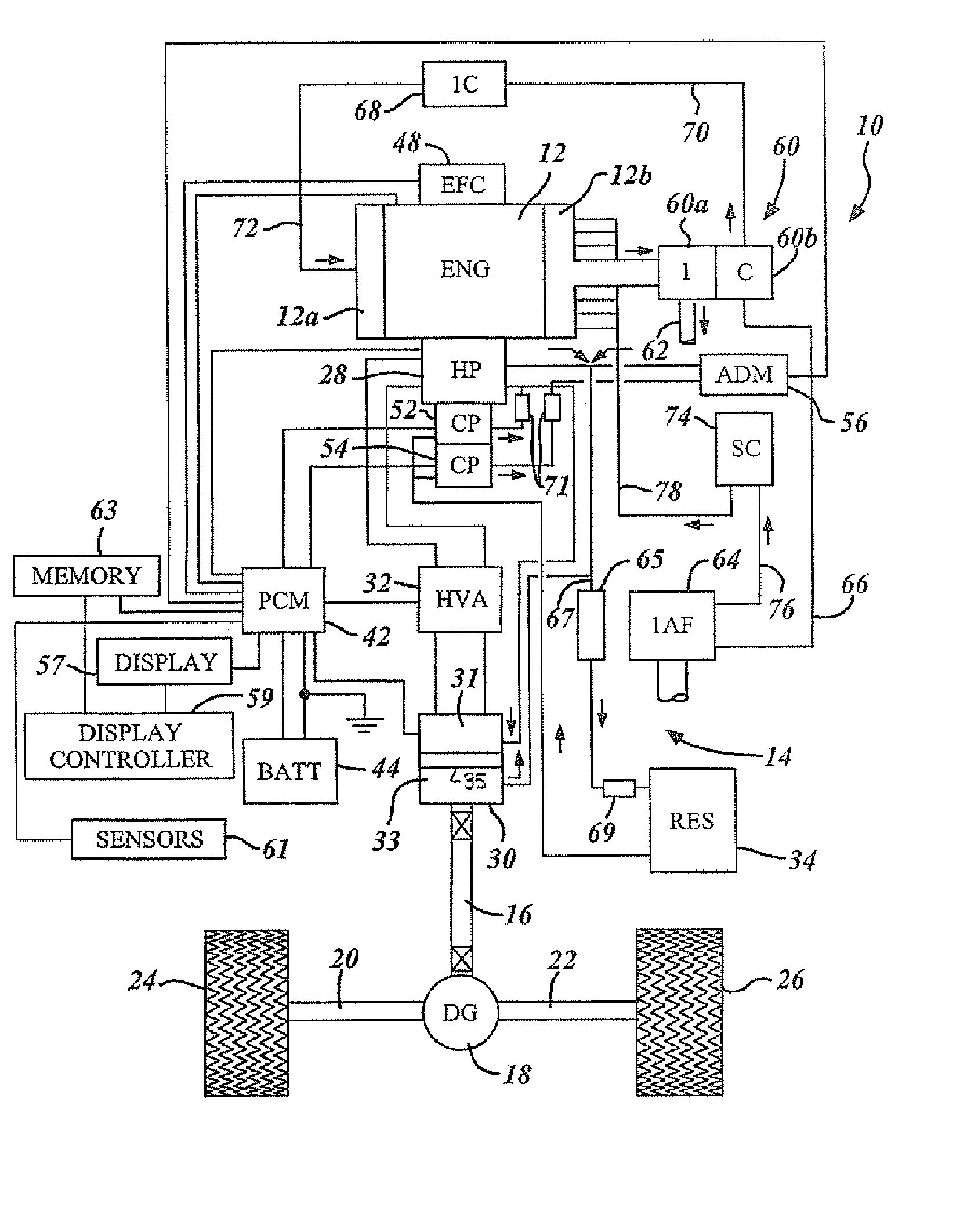
[0028] The present invention is disclosed herein primarily in the context of a roadway vehicle such as a truck equipped with a continuously variable hydrostatic drive. However, it will be understood that the invention is also useful both in other vehicular applications and in non-vehicular applications such as power generation stations.

[0029] In the following description, various operating parameters and components are described for one constructed embodiment. These specific parameters and components are included as examples and are not meant to be limiting.

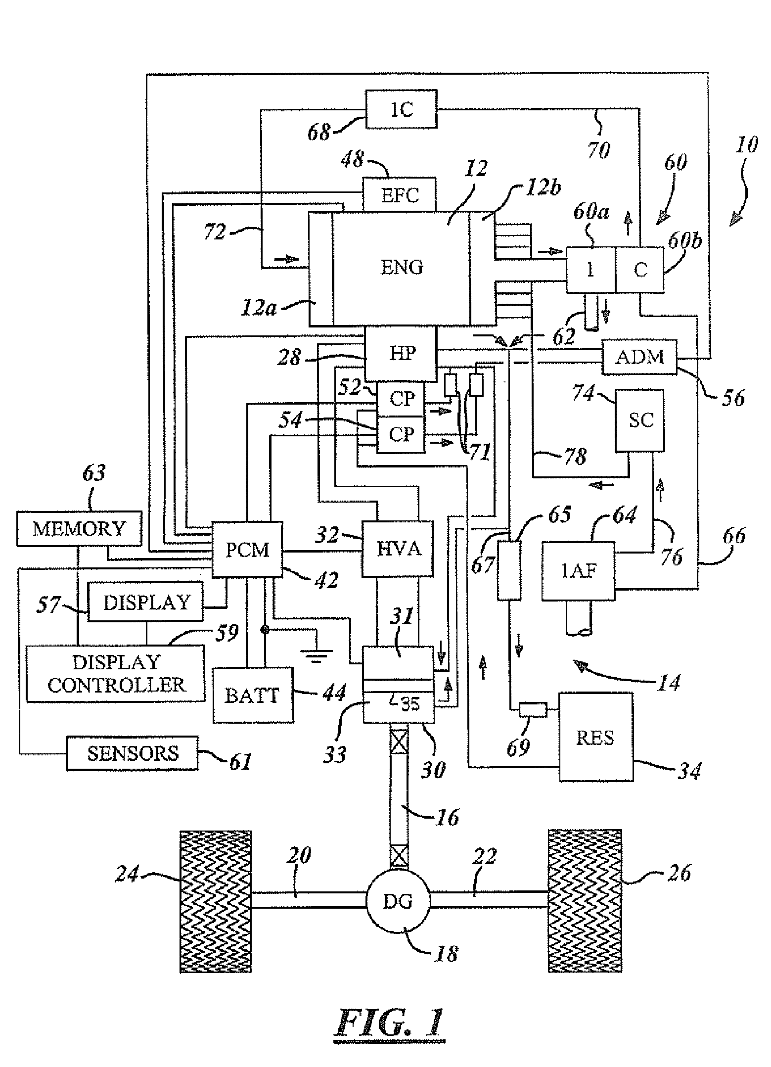
[0030] The present invention includes an engine, such as a turbocharged diesel engine, in which a high flow of above-atmospheric pressure air is injected into the engine exhaust manifold at distributed locations to simultaneously improve engine power output, exhaust emissions and fuel efficiency. In a sample embodiment, the injected air is provided by a supercharger, at a flow rate of approximately 100-250 cubic feet per minute...


PUM


Abstract

A method of controlling a powertrain of a vehicle includes the generation of an engine torque versus engine revolutions per minute (RPM) reference for an engine. A current engine speed is determined. A fuel input signal and a continuous variable transmission control signal are generated in response to the engine torque versus engine RPM reference and the current engine speed to maintain an approximately constant engine speed for various engine loading conditions.

Description

RELATED APPLICATION [0001] The present application claims priority to U.S. Provisional Application Ser. No. 60 / 587,575, filed Jul. 13, 2004, entitled “Energy Optimization of a System”, which is incorporated by reference herein.TECHNICAL FIELD [0002] The present invention relates to vehicle, hybrid, and hydraulic drive powertrain control systems. More particularly, the present invention is related to the efficient and simultaneous control of a vehicle engine and a continuous variable transmission, which may include hydraulic pumps and hydraulic drive motors. BACKGROUND OF THE INVENTION [0003] Conventional powertrains operate with significant energy loss, produce significant emissions, and have limited potential in fuel economy improvement. Much of the energy loss is due to a poor match between engine power capacity and average power demand. The load placed on the engine at any given instant is directly determined by the total road load at that instant, which varies between high and l...

Claims


Application Information

Patent Timeline
Patent Type & Authority Applications(United States)
IPC IPC(8): B60W10/04
CPCB60W10/06B60W10/103B60W30/188Y10T477/675F16H61/46F16H61/465B60W2710/0644
Inventor MITCHELL, HERMAN R.FLEMING, RAYMOND J.MCCLAIN, MARC
Owner SUPERDRIVE
Why Eureka
Try Eureka