
Traction adjustable cervical collar for transferring weight of the head of a wearer from the cervical spine of the wearer to the shoulders of the wearer

a cervical collar and adjustable technology, applied in the field of cervical collars, can solve the problems of not being suitable for the purpose, increasing neck related problems,

Inactive Publication Date: 2006-01-19
PILLAI BALA HARI
View PDF8 Cites 10 Cited by
  • Summary
  • Abstract
  • Description
  • Claims
  • Application Information

AI Technical Summary

Benefits of technology

[0015] ACCORDINGLY, AN OBJECT of the present invention is to provide a traction adjustable cervical collar for transferring weight of the head of a wearer from the cervical spine of the wearer to the shoulders of the wearer that avoids the disadvantages of the prior art.
[0017] STILL ANOTHER OBJECT of the present invention is to provide a traction adjustable cervical collar for transferring weight of the head of a wearer from the cervical spine of the wearer to the shoulders of the wearer that effectively complements chiropractic and manipulative therapy in whiplash injuries, degenerative diseases of the vertebrae and discs, herniated cervical discs, acute and chronic muscular problems, cervical nerve radiculopathy, and mild to severe neck pain from other causes where traction can be beneficial.

Problems solved by technology

The increased use of computers, travel, and driving, and the increase in sports and other trauma are causing an increase in neck related problems.
Furthermore, even though these innovations may be suitable for the specific individual purposes to which they address, however, they would not be suitable for the purposes of the present invention as heretofore described.

Method used


Image

  • Traction adjustable cervical collar for transferring weight of the head of a wearer from the cervical spine of the wearer to the shoulders of the wearer
  • Traction adjustable cervical collar for transferring weight of the head of a wearer from the cervical spine of the wearer to the shoulders of the wearer
  • Traction adjustable cervical collar for transferring weight of the head of a wearer from the cervical spine of the wearer to the shoulders of the wearer

Examples


Embodiment Construction

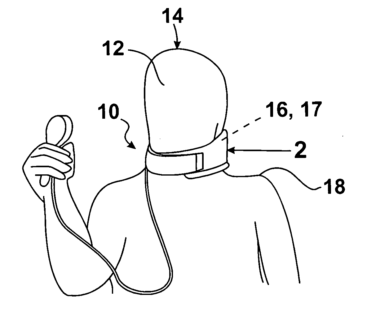
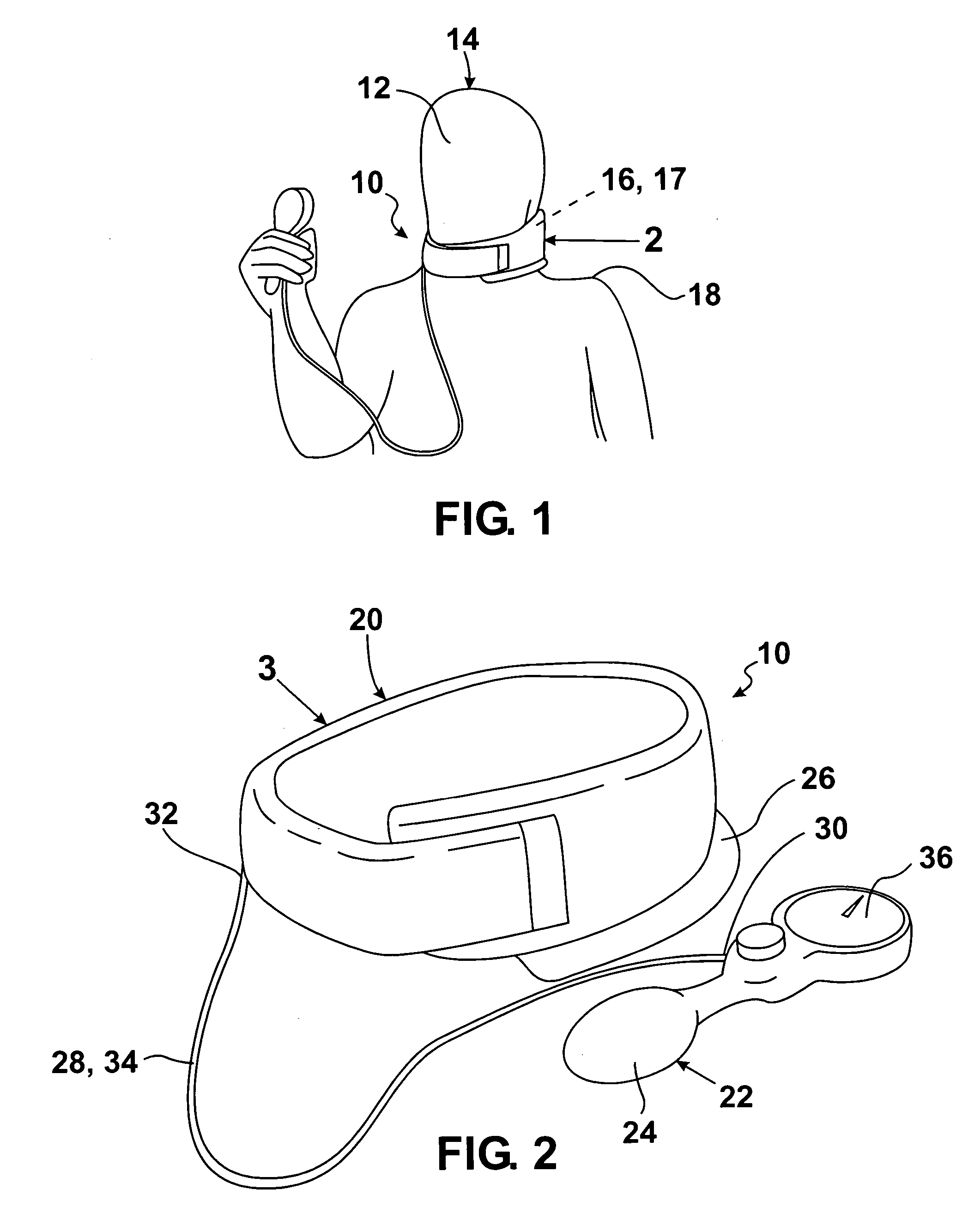
[0055] Referring now to the figures in which like numerals indicate like parts, and particularly to FIG. 1, which is a diagrammatic perspective view of the traction adjustable cervical collar of the present invention transferring weight of the head of a wearer from the cervical spine of the wearer to the shoulders of the wearer, the traction adjustable cervical collar of the present invention is shown generally at 10 for transferring weight of the head 12 of a wearer 14 from the cervical spine 16 of the neck 17 of the wearer 14 to the shoulders 18 of the wearer 14.

[0056] The general configuration of the traction adjustable cervical collar 10 can best be seen in FIG. 2, which is an enlarged diagrammatic perspective view of the traction adjustable cervical collar of the present invention identified by ARROW 2 in FIG. 1, and as such, will be discussed with reference thereto.

[0057] The traction adjustable cervical collar 10 comprises a collar portion 20 and inflating apparatus 22. The...


PUM


Abstract

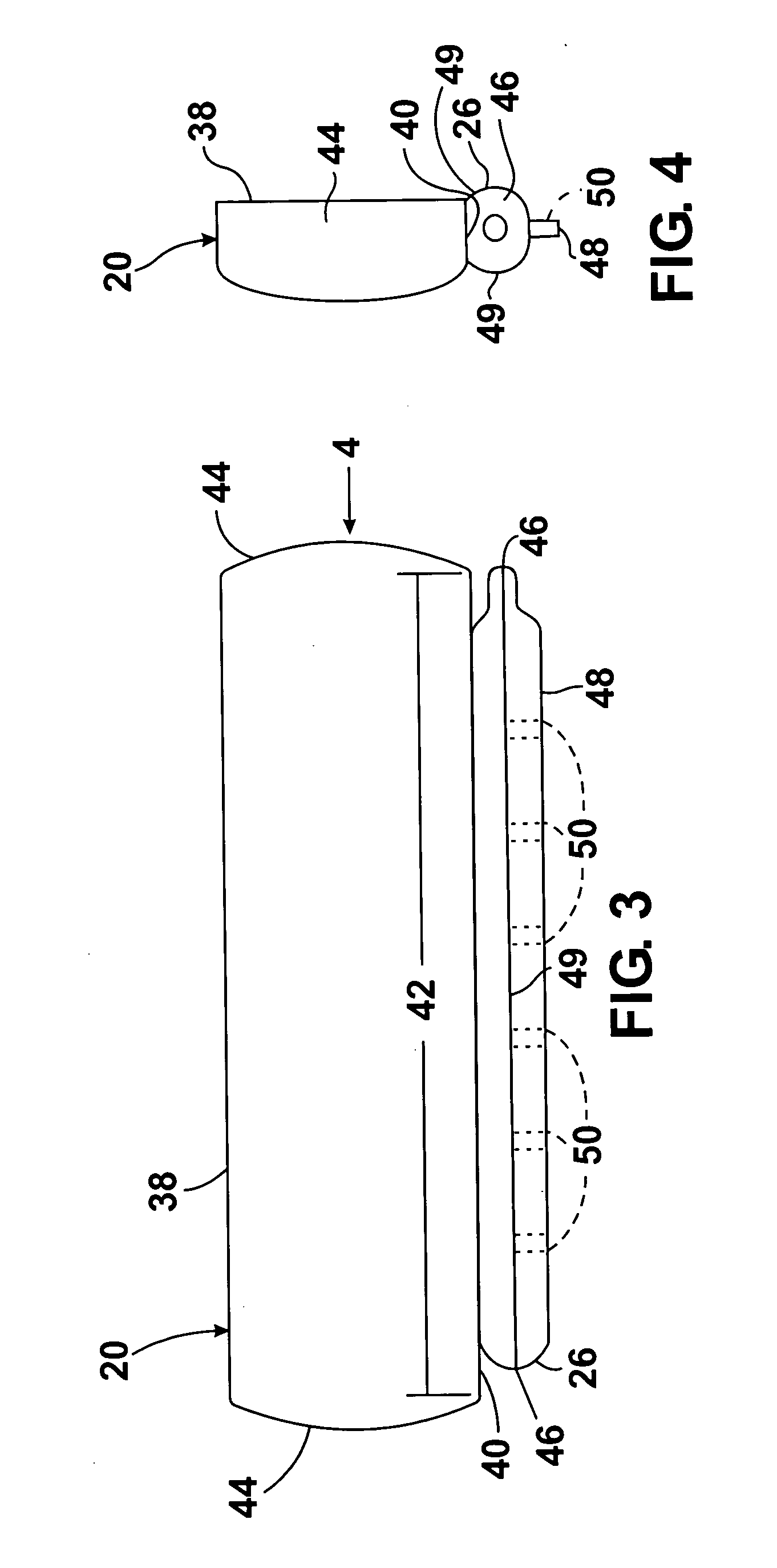
A traction adjustable cervical collar transferring weight of the head from the cervical spine to the shoulders. A collar portion releasably encircles the neck and is inflated by inflating apparatus. A bladder of the inflating apparatus is a part of the collar portion and a squeezable hand bulb of the inflating apparatus selectively inflates the bladder. The bladder has a lowermost surface that is flat for preventing slippage along the shoulders of the wearer. The bladder has a pair of side walls and contains a plurality of ribs extending upwardly from the lowermost surface thereof and which have a portion of the pair of side walls of the bladder adjacent thereto being attached thereto so as to provide rigidity to the bladder and prevent it from rolling over onto itself during use.

Description

BACKGROUND OF THE INVENTION [0001] 1. Field of the Invention [0002] The present invention relates to a cervical collar, and more particularly, the present invention relates to a traction adjustable cervical collar for transferring weight of the head of a wearer from the cervical spine of the wearer to the shoulders of the wearer. [0003] 2. Description of the Prior Art [0004] About 10% of the adult population suffers from neck pain of some type from time to time. The increased use of computers, travel, and driving, and the increase in sports and other trauma are causing an increase in neck related problems. [0005] Pain may be moderate to severe and may be localized to the neck area or radiate to surrounding tissues. The actual origin of the pain could come from the spinal cord or its roots, the spinal column, the intervertebral discs, or the other support and soft tissue around the neck. [0006] Numerous innovations for cervical orthopaedic devices have been provided in the prior art ...

Claims


Application Information

Patent Timeline
Patent Type & Authority Applications(United States)
IPC IPC(8): A61F5/00
CPCA61F5/055A61F5/012
Inventor PILLAI, BALA HARI
Owner PILLAI BALA HARI
Learn More