
I-beam configuration bone plate

Inactive Publication Date: 2006-01-19
KLS MARTIN LP
View PDF14 Cites 169 Cited by
  • Summary
  • Abstract
  • Description
  • Claims
  • Application Information

AI Technical Summary

Benefits of technology

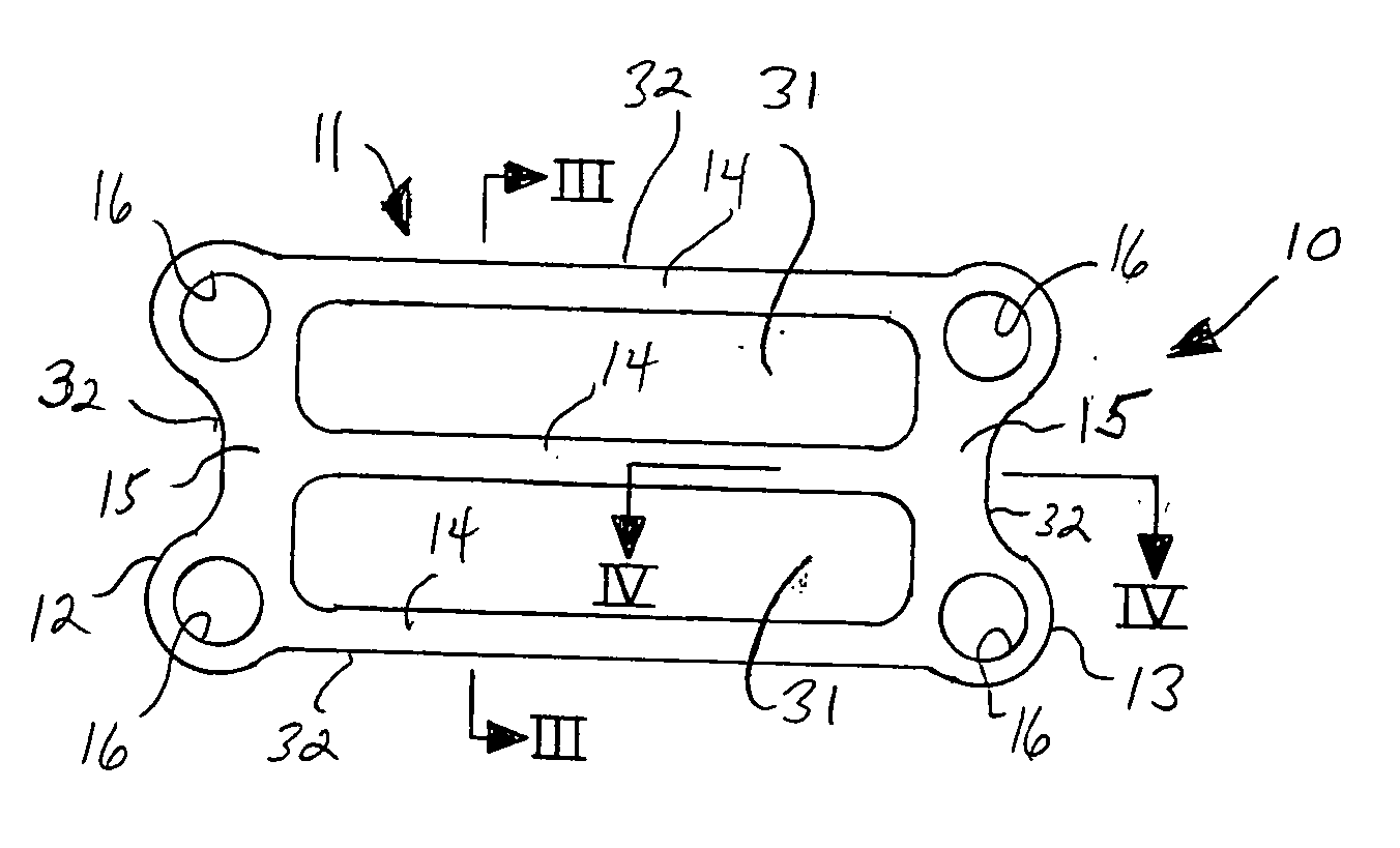
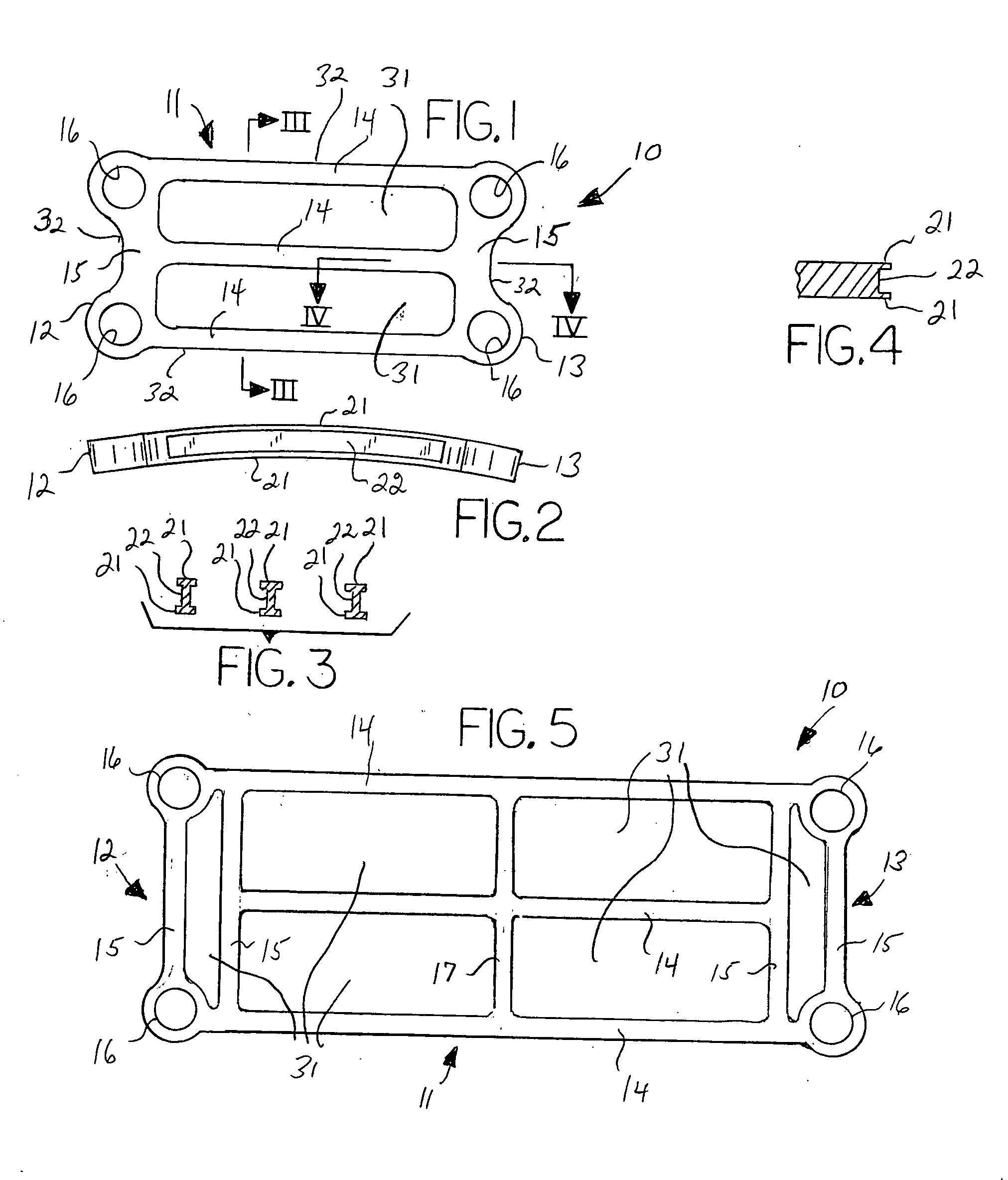
[0007] The bone plate is typically composed of metal, although other materials possessing sufficient strength and rigidity may also be suitable, and comprises opposing screw-receiving apertures, preferably in plural sets, adapted to receive bone screws for securing the bone plate to the adjacent bones or bone segments. The bone plate body is a relatively thin member with length and width dimensions greatly exceeding the thickness dimension, typically flat or slightly curved depending on the application, and comprises at least one bridging member that extends between the opposing ends of the bone plate containing the screw-receiving apertures and spanning members that extend between the screw-receiving apertures on each of the opposing ends of the bone plate. Preferably, the bone plate body comprises a plurality of bridging members, such that the bridging members define one or more interior openings within the bone plate body and / or one or more lateral recesses. One or preferably all of the bridging members have an I-beam configuration in cross-section, such that each bridging member comprises a pair of generally parallel surface members joined by a generally perpendicularly disposed bracing member. Most preferably, the spanning members are constructed having an I-beam or a half I-beam configuration as well. In this manner, the overall mass of the bone plate and the area obscured by the bone plate are reduced without reducing the strength and rigidity of the bone plate in comparison to a bone plate having a solid body.

Problems solved by technology

This can be addressed by providing open spaces within the body of the bone plate, but the amount of open area is limited by the need to retain sufficient strength and rigidity in the main body.

Method used


Image

  • I-beam configuration bone plate
  • I-beam configuration bone plate

Examples


Embodiment Construction

[0013] With reference to the drawings, the invention will now be described with regard for the best mode and the preferred embodiment. In general, the invention comprises a bone fixation plate composed of a biocompatible material that is suitable for securing together in a fixed and rigid manner two bones or bone segments such that relative movement between the two bones or bone segments is precluded, such as for example the fixation of adjacent vertebrae, or the fixation of adjacent bone segments when a bone has been fractured, or the fixation of adjacent bone segments when a bone has been surgically severed during a medical procedure. For ease of reference in this disclosure, the term “bone segment” shall be taken to include bones, bone fragments, bone sections or the like.

[0014] The bone plate 10 is a generally flat, as shown in FIG. 1, or curved member, as shown in FIG. 2, composed of a metal or similar biocompatible material having good strength and rigidity characteristics, s...


PUM


Abstract

A bone plate having a first opposing end containing screw-receiving apertures and a second opposing send containing screw-receiving apertures, the first opposing end and the second opposing end being joined by a plurality of bridging members, the bridging members having an I-beam configuration in cross-section and defining at least one opening in the main body of the bone plate.

Description

[0001] This application claims the benefit of U.S. Provisional Patent Application Ser. No. 60 / 589,091, filed Jul. 19, 2004.BACKGROUND OF THE INVENTION [0002] This invention relates generally to the field of bone plate fixation devices that are used to secure bones or separated bone segments in a rigid and fixed relationship, usually so that osteosynthesis or bone regeneration may occur. [0003] Orthopedic fixation devices in the form of flat or slightly curved plates are well known and are used to fix and secure adjacent bones or bone segments in a rigid manner, such as for example to maintain adjacent vertebrae in a fixed manner relative to each other, or to maintain fractured or surgically cut bone segments in a fixed manner relative to each segment such that bone regeneration may occur. One common application is to apply a bone plate to a sternum that has been cut in order to provide access to the heat, for example. The bone plates are typically composed of a biocompatible, solid-...

Claims


Application Information

Patent Timeline
IPC IPC(8): A61F2/30
CPCA61B17/7059A61B17/8085A61B17/8076A61B17/80
Inventor BURKE, SHAWN
Owner KLS MARTIN LP
Learn More