
Drive for magnetic tape adjustable for use with tapes of different widths

Active Publication Date: 2006-01-26
TANDBERG DATA STORAGE
View PDF9 Cites 0 Cited by
  • Summary
  • Abstract
  • Description
  • Claims
  • Application Information

AI Technical Summary

Benefits of technology

[0014] In a further embodiment of the reel assembly, two such elements are formed by two curved arms that are each pivotably mounted to an expandable/compressible element, such as a telescoping element, disposed in the hub of the reel assembly. Each of these curved arms has a pin at the end thereof, which projects through a curved opening in one of the flanges, these pins projecting above the exterior surface of this flange. The compressible/expandable element is spring-biased so as to normally force these pins to their extreme outwardly radial position, with the respective pins at the radial ends of the respective slots in the flange. When so deployed, the presence of these curved arms decreas

Problems solved by technology

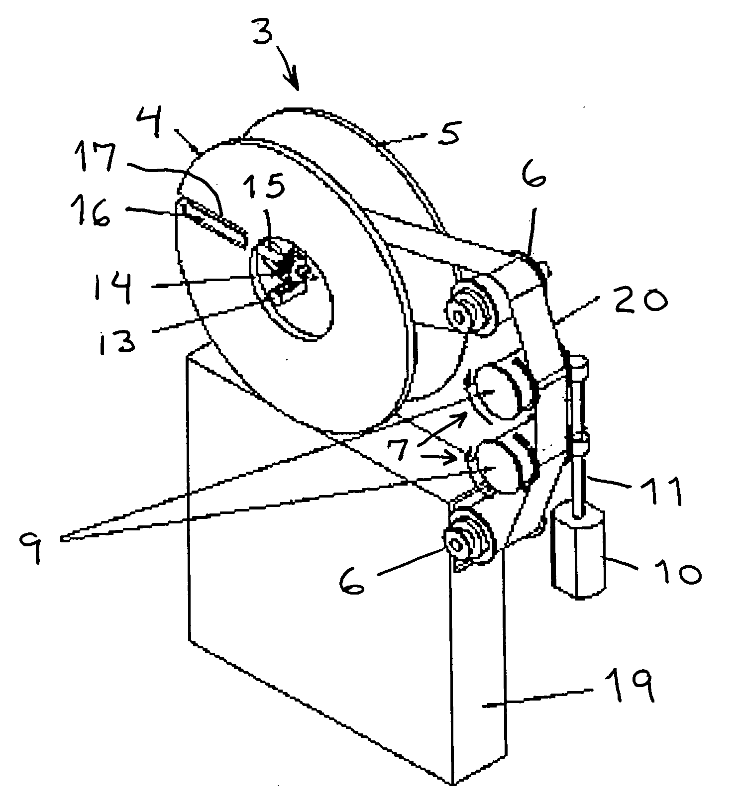
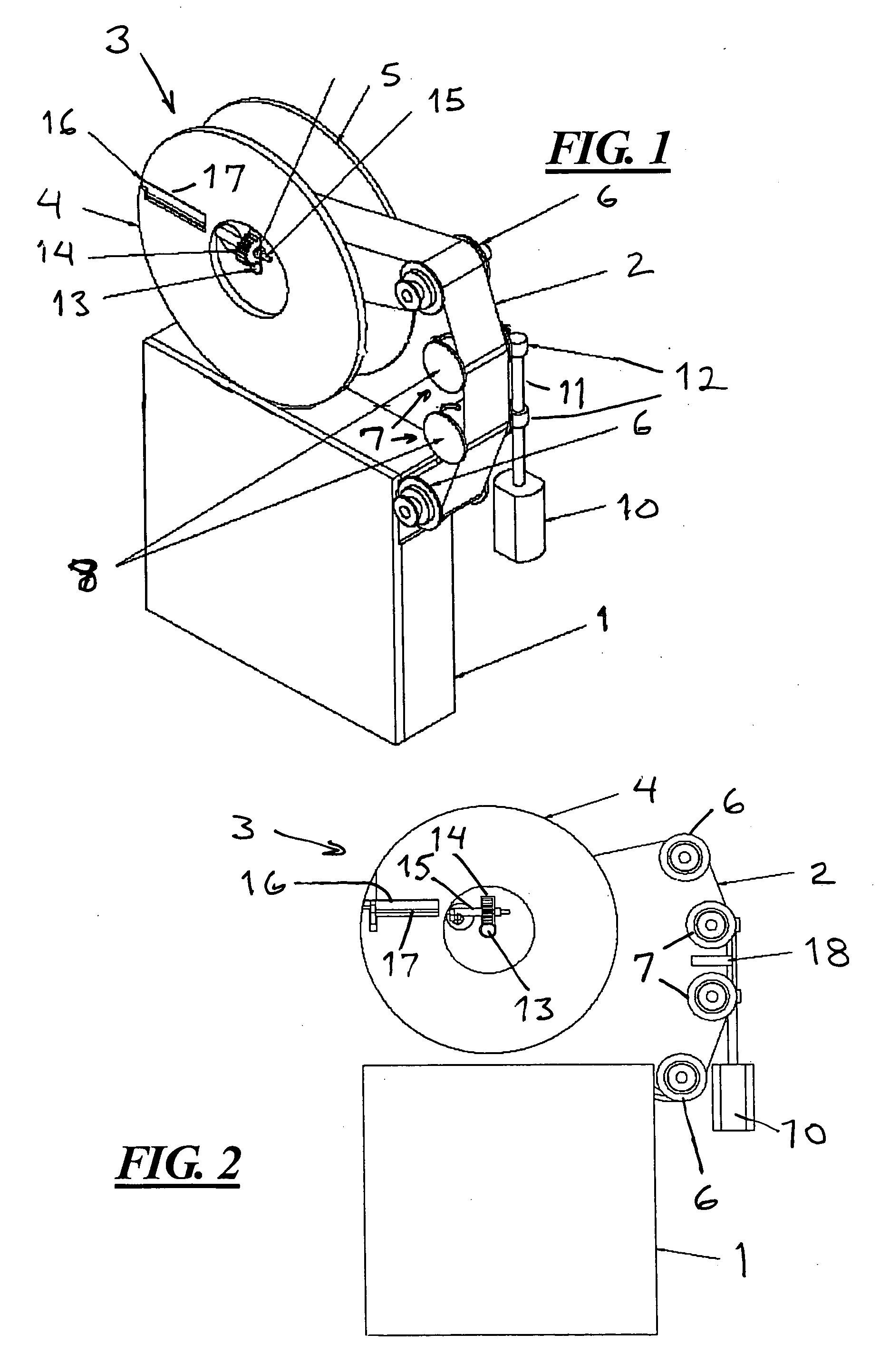
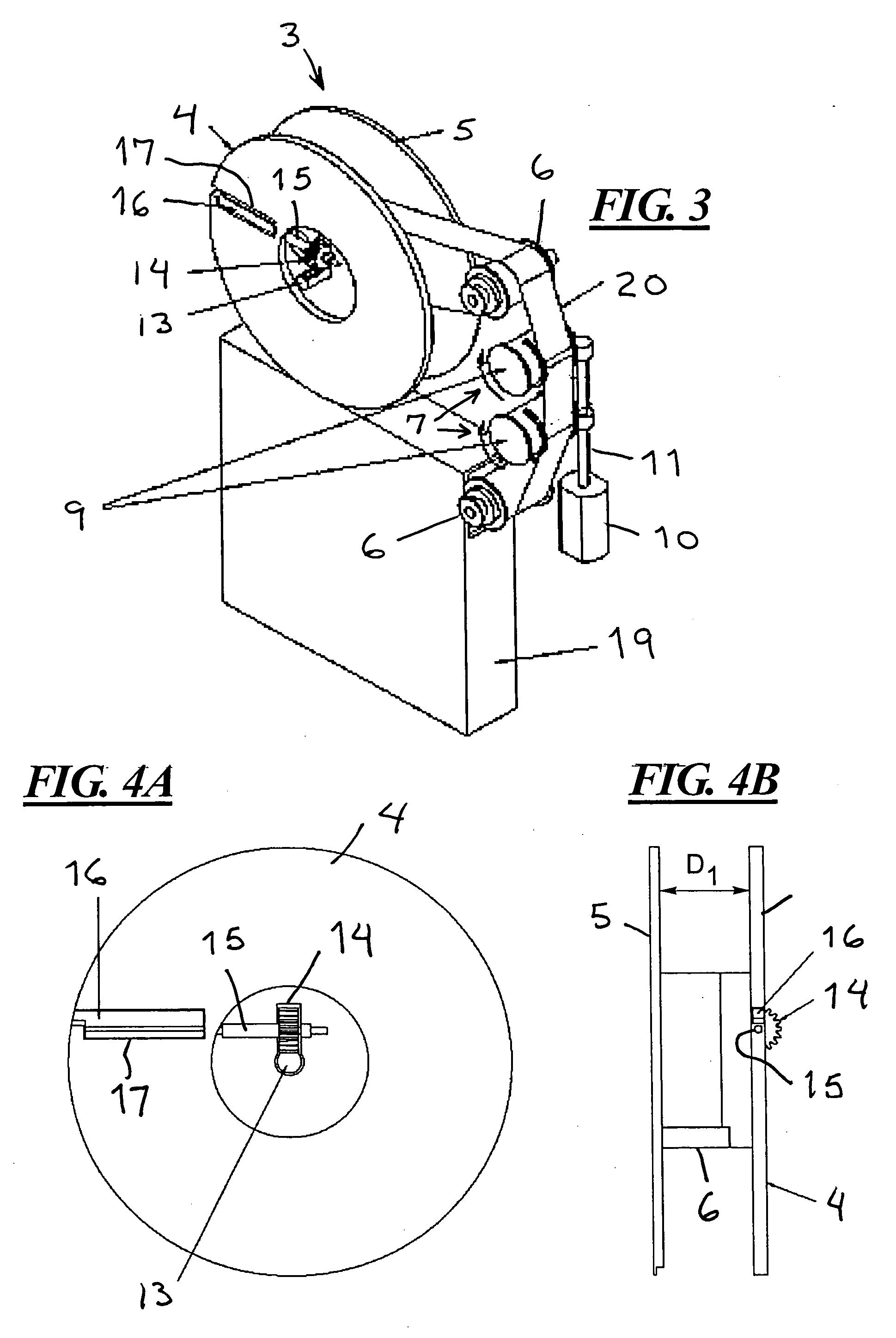
A problem associated with such interchangeable operation, however, is that the take-up reel in the tape drive must be designed to accommodate the widest tape width that will be used with the tape drive.
This means that when tape of the narrower width is used, the internal dimension of the take-up reel (between the flanges) will be larger than the width of the narrow tape, and as the narrow tape is wound on such a reel, it will tend to meander or wander as it is wound on the hub.
Such guides, therefore, would not be effective for accurately guiding the narrower tape.

Method used


Image

  • Drive for magnetic tape adjustable for use with tapes of different widths
  • Drive for magnetic tape adjustable for use with tapes of different widths
  • Drive for magnetic tape adjustable for use with tapes of different widths

Examples


second embodiment

[0033] A second embodiment for the spacing setting arrangement is shown in FIGS. 6A, 6B, 6C, FIG. 7, FIGS. 8A, 8B and 8C, and FIGS. 9A, 9B and 9C. In this embodiment, as shown in FIGS. 6A, 6B and 6C, one of the flanges 4A carries two curved ribs 21 thereon, each mounted to a pivoting arrangement disposed in the hollow interior of the hub 6A. This pivoting arrangement includes an expandable contractible element 27 such as (in the exemplary embodiment) a telescoping element composed of telescoping members 23 and 24. The outer ends of the respective telescoping members 23 and 24 are attached by pivot pins 25 to pivot arms of the curved ribs 21. Each pivot arm joins the curved part of the curved rib 21 and a junction, which rotates around a pivot pin 26 projecting from the hub 6A. The expandable / contractible member 27 is rotatable around a central axle (not shown) in the hub 6A. A spring (not shown) is disposed in the hollow interior of the telescoping members 23 and 24, forcing them ap...

first embodiment

[0034] An actuatable slide arm 26 is mounted in the drive, and is actuatable under the same conditions as the aforementioned rack 13 in the The slide arm 29 in the exemplary embodiment is normally in a position relative to the reel assembly 3 as shown in FIG. 6B. When actuated, it begins to move through the position shown in FIG. 7, and eventually comes to the position shown in FIG. 8B.

[0035] Each curved rib 21 carries a pin 22 at the free end thereof. These pins 22 slide in curved slots 28 in the flange 5A of the reel assembly 3, as shown in FIGS. 9A, 9B and 9C. The pins extend through these slots 28, and project slightly above the exterior surface of the flange 5A. As the slide arm 29 is actuated and the reel assembly 3 is rotated, the pins 22 come to abut against the slide arm 29, and as the reel assembly 3 continues to rotate, the pins 22 are forced to follow the curved slots 28, thereby forcing the curved ribs 21 against the force of the spring bias, so as to cause the curved ...


PUM


Abstract

A tape drive has a take-up reel assembly and a tape guide arrangement that are each selectively actuatable for interchangeable use with magnetic recording tape of a first width or a second width. The take-up reel assembly includes at least one actuatable, retractable element that can be moved between the flanges of the take-up reel assembly, dependent on the width of the tape currently being used in the drive, and the tape guide arrangement includes actuatable guide elements movable to define a width of the tape transport path across the read / write head, also dependent on the width of the magnetic recording tape currently being used.

Description

BACKGROUND OF THE INVENTION [0001] 1. Field of the Invention [0002] The present invention relates in general to tape drives, and in particular to a tape drive that can accept magnetic recording tapes of different widths. [0003] 2. Description of the Prior Art [0004] Magnetic tape drives and magnetic tape cartridges are manufactured with standardized dimensions, conforming to an industry-wide form factor, so a standardized magnetic tape cartridge having a particular form factor can always be accepted in a drive designed for that form factor. [0005] Data are magnetically recorded on a tape in adjacent tracks proceeding parallel to the longitudinal length of the tape. The access time to data that are stored at a location that is at some distance from one end of the tape is dependent on the time required to wind or unwind the tape to bring that particular location to a position in front of the read head. In order to reduce this access time, so-called wide tape cartridges have been devel...

Claims


Application Information

Patent Timeline
IPC IPC(8): G11B23/04
CPCG11B15/60G11B15/67G11B15/66
Inventor RUDI, GUTTORM
Owner TANDBERG DATA STORAGE
Learn More