Terminal block structure and stator for resolver

Active Publication Date: 2015-12-31
MINEBEAMITSUMI INC
View PDF11 Cites 0 Cited by
  • Summary
  • Abstract
  • Description
  • Claims
  • Application Information

AI Technical Summary

Benefits of technology

[0013]According to the present invention, a terminal block structure for decreasing the width of a terminal block, and a resolver stator having the terminal block structure, are provided. According to the terminal block structure, a space between the external connecting te

Problems solved by technology

Therefore, according to the terminal shape disclosed in Japanese Unexamined Patent Application Laid-Open No. 2010-175349, since decreasing the pitch of the exter

Method used


Image

  • Terminal block structure and stator for resolver
  • Terminal block structure and stator for resolver
  • Terminal block structure and stator for resolver

Examples


Example

(1-1) Structure of First Embodiment

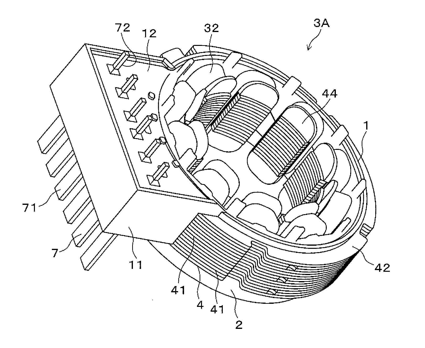
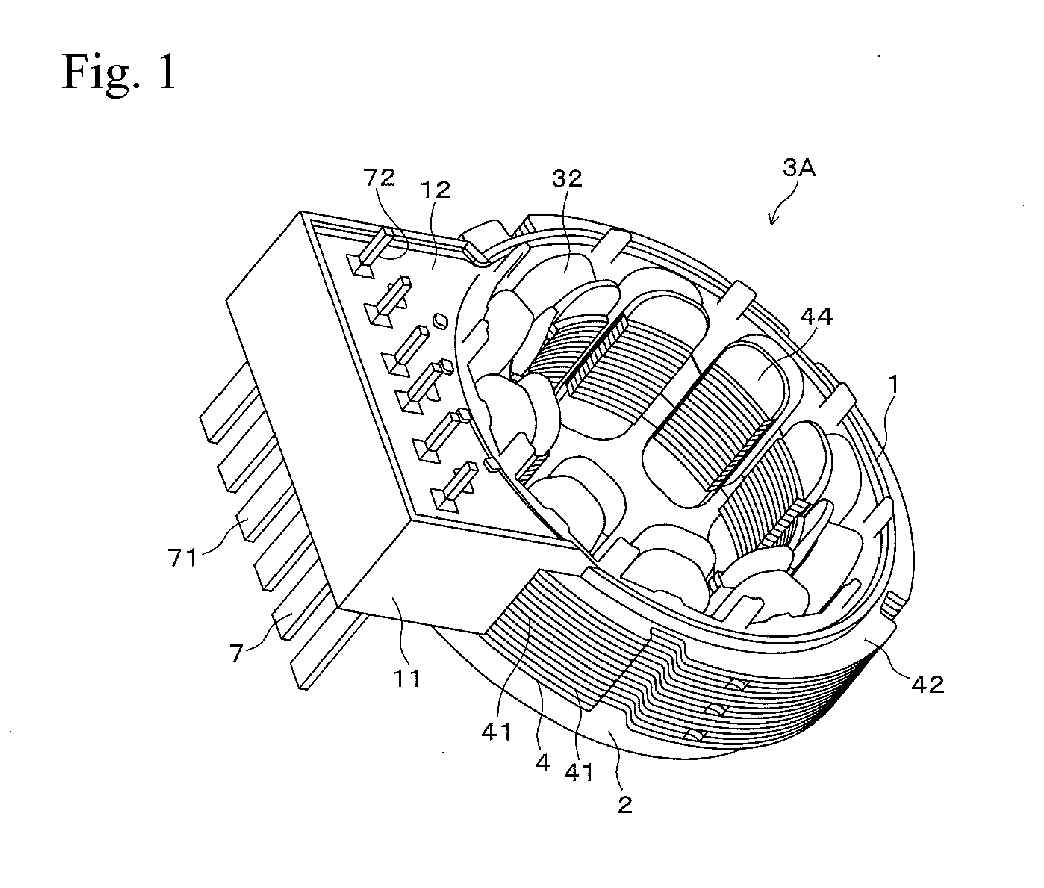
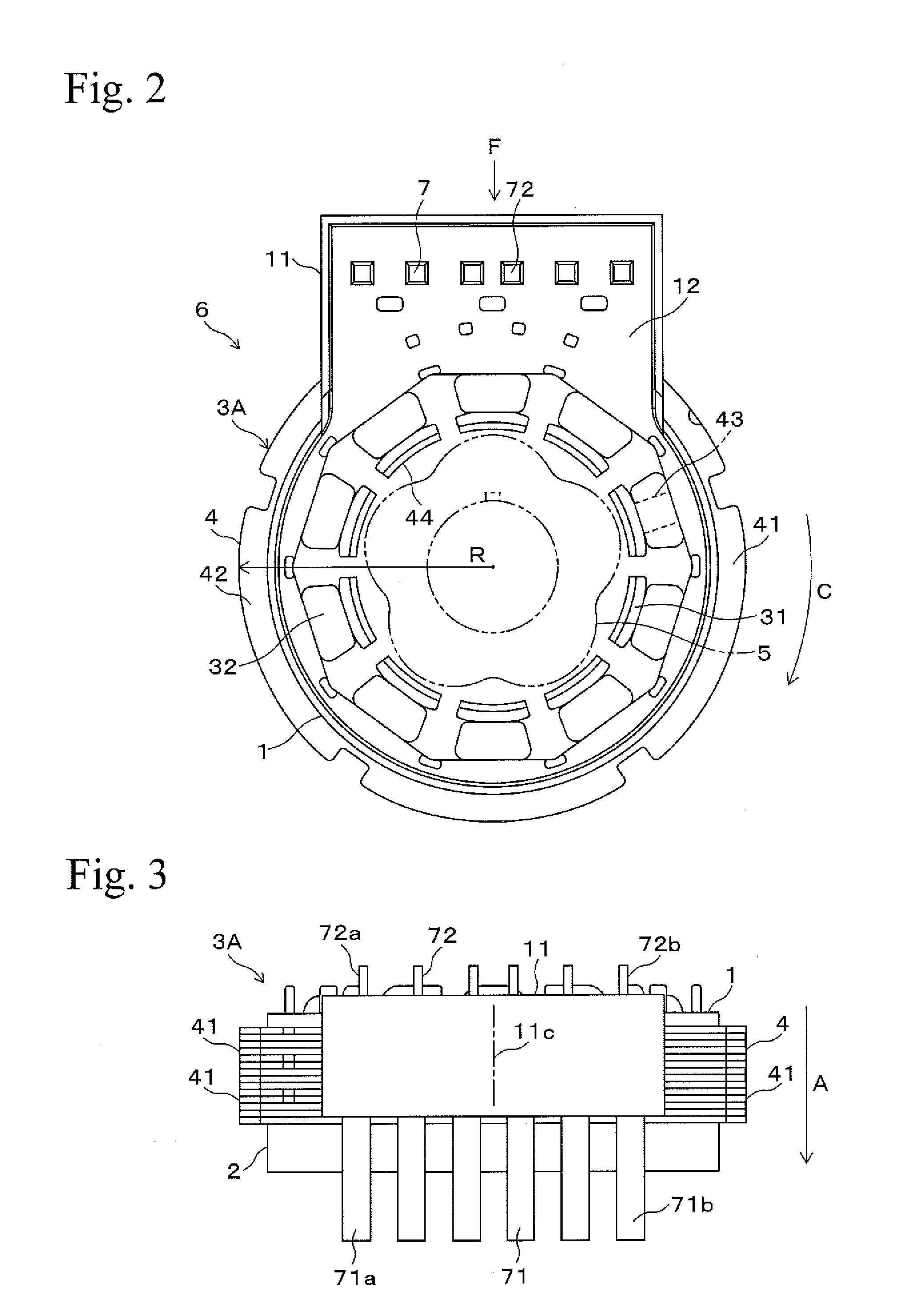
[0024]FIGS. 1 to 3 show a stator 3A of a resolver 6 of an embodiment. The stator 3A includes a circular stator core 4 and includes a first insulator 1 and a second insulator 2, which are attached so as to hold the stator core 4 from both sides in the axial direction. As shown in FIG. 2, the resolver 6 is constructed by providing a rotor 5 inside the stator 3A. The rotor 5 has a shaft center at which an output shaft of a motor (not shown in the figures) is fixed, and the resolver 6 is used as a sensor for detecting a rotation angle of the motor. In the following descriptions, the “circumferential direction” and the “radial direction” are defined as the directions indicated by the symbols “C” and “R” in FIG. 2, respectively, regarding the circular stator 3A. In addition, the “axial direction” is defined as the direction indicated by the symbol “A” in FIG. 3 regarding the circular stator 3A.

[0025]The stator core 4 is formed by laminating plural circul...


PUM


Abstract

The width of a terminal block is decreased by decreasing a space between an external connecting terminal at each end of the external connecting terminals and an end portion of the terminal block, whereas a space between a winding terminal at each end of the winding terminals of terminals and an end portion of the terminal block is sufficiently obtained. A terminal 7 is provided with an external connecting terminal 71 and a winding terminal 72, and the terminal 7 has a shape such that a center line Lp in the width direction of the winding terminal 72 is shifted from a center line Le in the width direction of the external connecting terminal 71. A plurality of the terminals 7 are arranged on a terminal block 11 so that pitches between the winding terminals 72 are unequal.

Description

BACKGROUND OF THE INVENTION[0001]1. Field of the Invention[0002]The present invention relates to a terminal block structure for a resolver having a terminal block with plural terminals and relates to a resolver stator provided with the terminal block structure.[0003]2. Description of Related Art[0004]For example, resolvers are used as sensors for detecting rotation angle of motors mounted in electric vehicles, hybrid vehicles, or the like. Such types of resolvers are generally provided with a rotor, a stator, a pair of insulators, and coils. The rotor is secured to a rotating shaft of a motor so as to able to rotate. The stator is fixed to a housing and is arranged outside the rotor. The insulators are attached so as to hold the stator from both sides in the axial direction. The coils include an exciting coil and a detecting coil and are wound around magnetic insulating portions of the insulators. When the rotor rotates, the dimension of air gap formed between the rotor and the stat...

Claims


Application Information

Patent Timeline
IPC IPC(8): G01D5/20
CPCG01D5/20
Inventor OTOBE, HARUKI
Owner MINEBEAMITSUMI INC
Why Eureka
Try Eureka