Metal line layout of an integrated circuit

Inactive Publication Date: 2005-03-15
MICRON TECH INC
View PDF25 Cites 5 Cited by
  • Summary
  • Abstract
  • Description
  • Claims
  • Application Information

AI Technical Summary

Benefits of technology

The inventive process enhances metal line layout designs by providing two separate control spaces for the Werner Fill process along speed sensitive pathways. Speed sensitive pathways are defined by long, substantially parallel metal lines that typically extending over 10 μm in length. One control space (i.e., DRCgap1) is for decreasing the spacing between various metal features to standardize such spacing according to the Werner Fill process. A second control space (i.e., DRCgap2) is for addressing capacitance issues along speed sensitive pathways. For example, for a speed sensitive pathway where there are two long parallel adjacent metal lines, the Werner Fill process would bring the space between these lines down to a space defined by DRCgap1 by adding metal line features or spacers. Instead, according to the present invention, the added metal line features or spacers provide a fundamental space between these lines of DRCgap2, which is defined to be somewhere between DRCgap1 and the maximum space that will still be readily fillable with IDL, and thus without negatively impacting the Werner Fill process. At the ends of the long parallel metal lines, the spacing of the added metal line features, or spacers, is reduced to the fi

Problems solved by technology

However, as semiconductor device geometries continue to decrease in size, providing more devices per fabricated wafer, capacitance between metal line features (dummy and/or live) becomes an issue.
Since delay of a signal through a metal line is directly proportional to capacitance, and capacitance is inversely proportional to spa

Method used


Image

  • Metal line layout of an integrated circuit
  • Metal line layout of an integrated circuit
  • Metal line layout of an integrated circuit

Examples


Example

Skilled artisans appreciate that elements in the figures are illustrated for simplicity and clarity and have not necessarily been drawn to scale. For example, the dimensions of some of the elements in the figures may be exaggerated relative to other elements to help to improve understanding of the various embodiments of the present invention.

DETAILED DESCRIPTION OF THE PREFERRED EMBODIMENTS

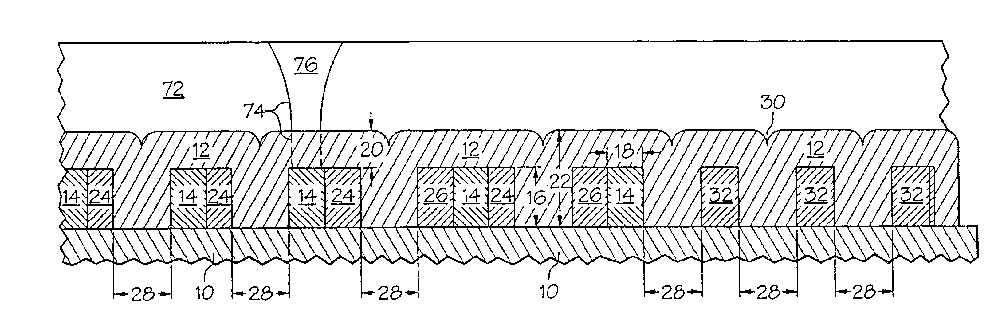
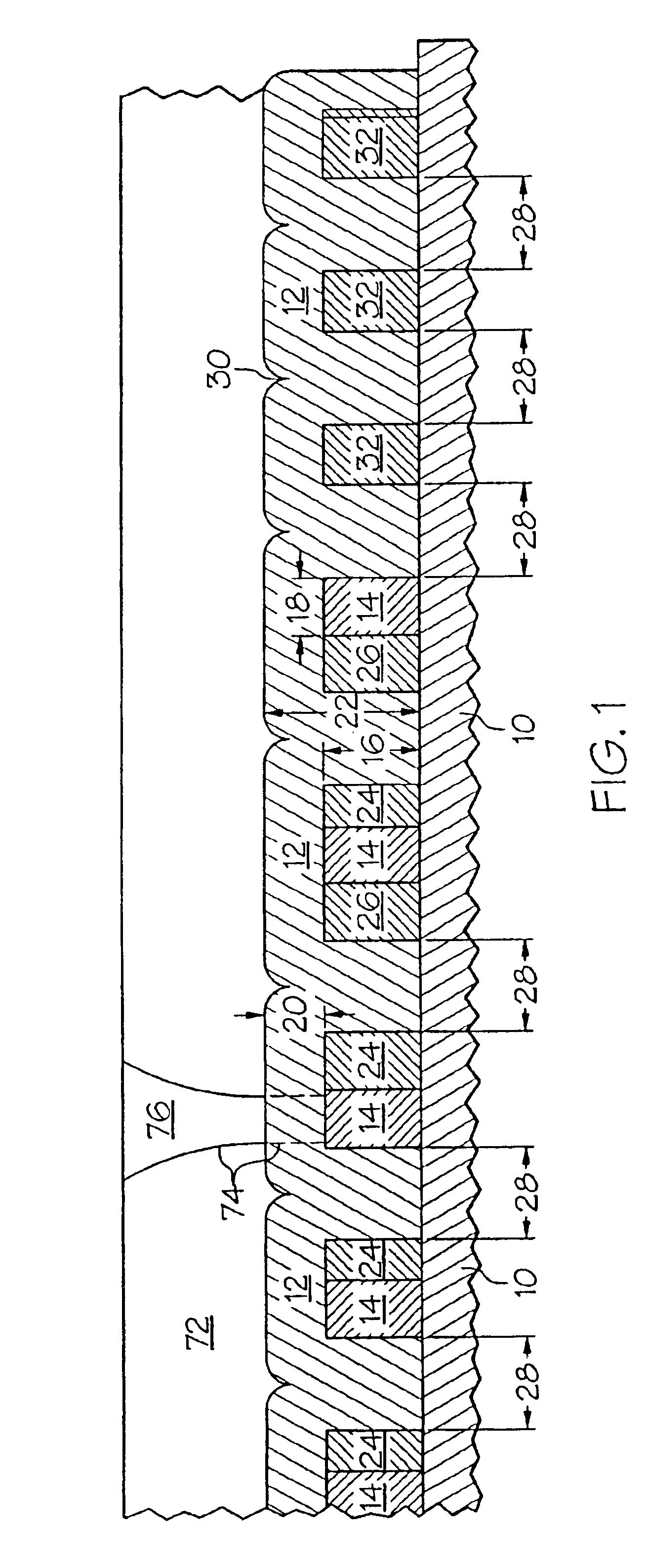
FIG. 1 depicts in cross section, an integrated circuit structure with a metal line layout design having standardized spaces between nearest metal features thereon according to the Werner Fill process. As previously mentioned, commonly assigned U.S. Pat. No. 5,981,384, discloses the Werner Fill process, of which the entire disclosure is incorporated fully by reference. Additionally, sections of that disclosure are reproduced hereinafter for better understanding of the inventive modification made to the Werner Fill process. Furthermore, as used herein the term “metal features” refers to all metal fe...


PUM


Abstract

A metal line layout which includes two separate control spaces to address capacitive issues along speed sensitive pathways in an integrated circuit structure without negatively impacting Werner Fill processing. One control space (i.e., DRCgap1) is for decreasing the spacing between various metal features to standardize such spacing, and a second control space (i.e., DRCgap2) is for addressing capacitance issues along speed sensitive pathways. Between speed sensitive pathways, spacing of added metal features provided to long parallel metal lines are maintained at the second control spacing DRCgap2. Spaces at the ends of such long parallel metal lines are reduced to the first control spacing DRCgap1 in order to best fill three-way-intersections (TWIs) with subsequent depositions.

Description

BACKGROUND OF THE INVENTIONThis invention relates to metal lines of an integrated circuit (IC), and more particularly relates to spacing metal lines in an integrated circuit to minimize capacitive issues along speed sensitive pathways in a random access memory structure to reduce signal delay without negatively impacting Werner Fill processing.The Werner Fill process is disclosed by commonly owned U.S. Pat. No. 5,981,384, the disclosure of which is herein fully incorporated by reference. The Werner Fill process modifies the layout of electrically unisolated or live metal lines so that the spacing between the metal lines is substantially standardized prior to performing deposition of an intermetal dielectric layer (IDL). According to the Werner Fill process, circuit layout design modifications are made by adding dummy metal line features in areas of the layout having open spaces between parallel metal lines, and adding metal line spacers to existing metal lines to reduce the spacing ...

Claims


Application Information

Patent Timeline
IPC IPC(8): H01L21/70H01L23/52H01L23/522H01L21/768H01L23/528
CPCH01L21/76819H01L23/5283H01L23/528H01L23/5222H01L2924/0002
Inventor IRELAND, PHILIP J.
Owner MICRON TECH INC
Why Eureka
Try Eureka