

Systems and methods for displaying images and processing work pieces
a technology of work pieces and systems, applied in the field of systems and methods for displaying images, can solve the problems of inefficient use of materials and time-consuming processes
- Summary
- Abstract
- Description
- Claims
- Application Information
AI Technical Summary
Problems solved by technology
Method used
Image

Examples
Embodiment Construction
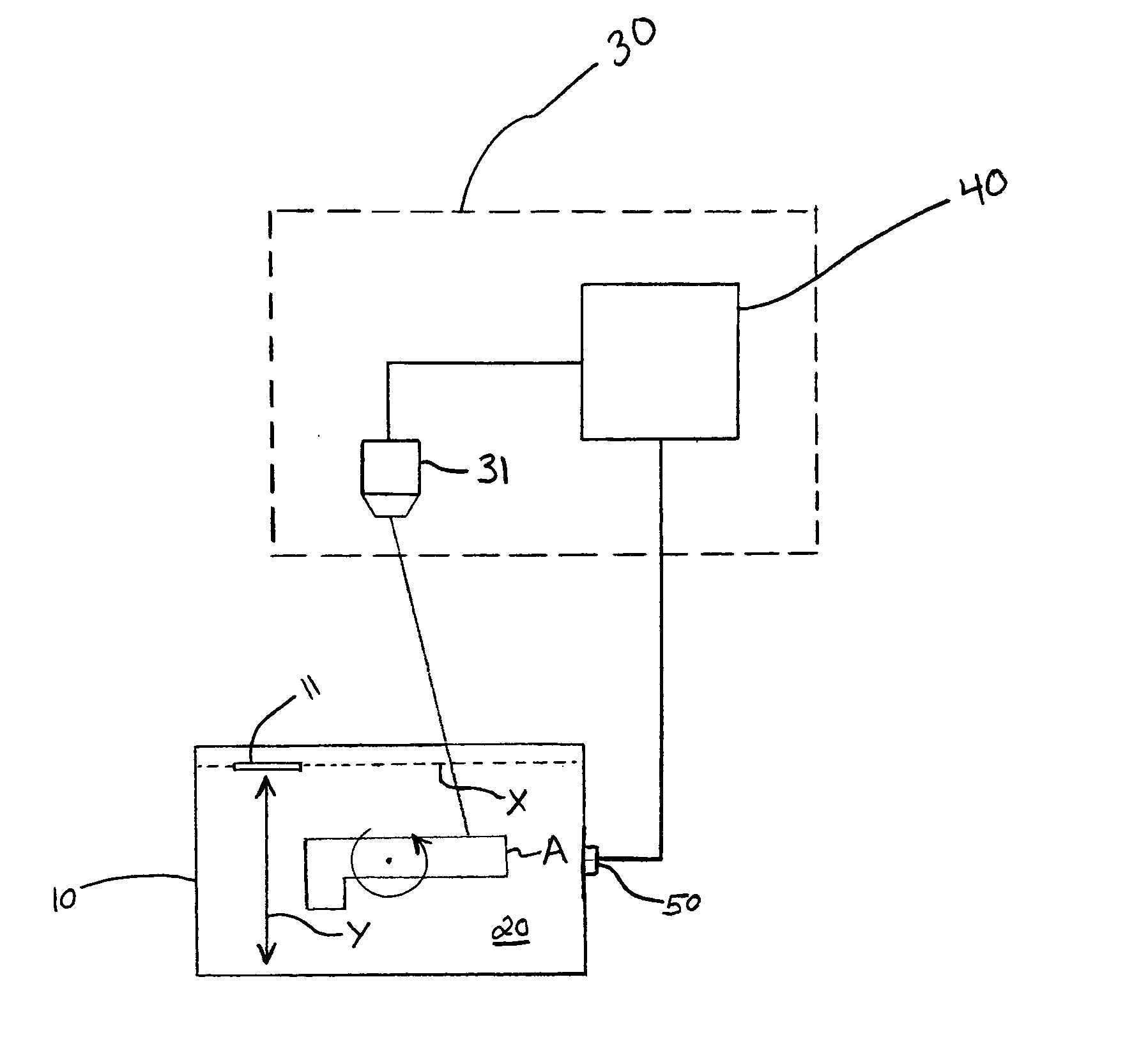
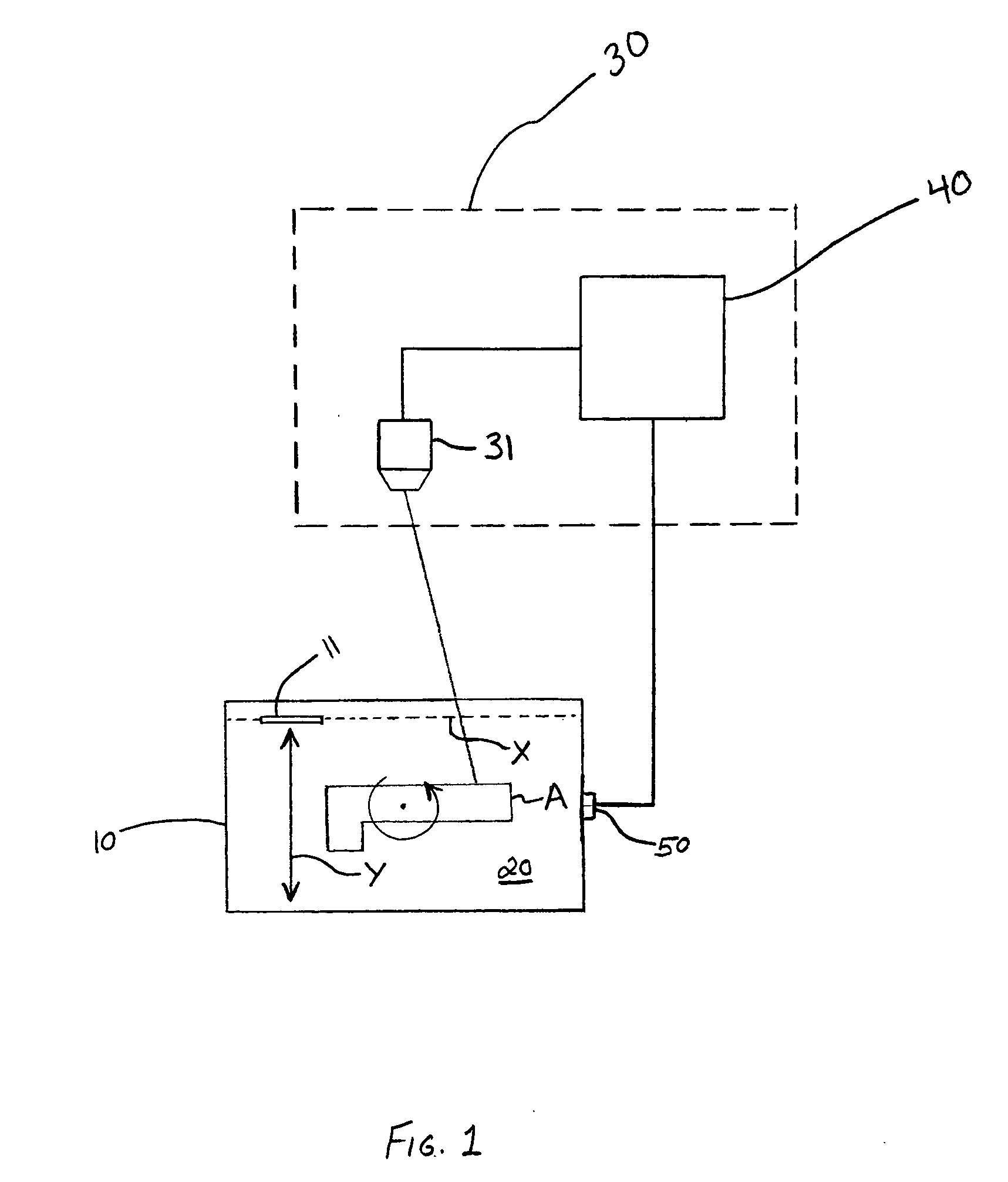
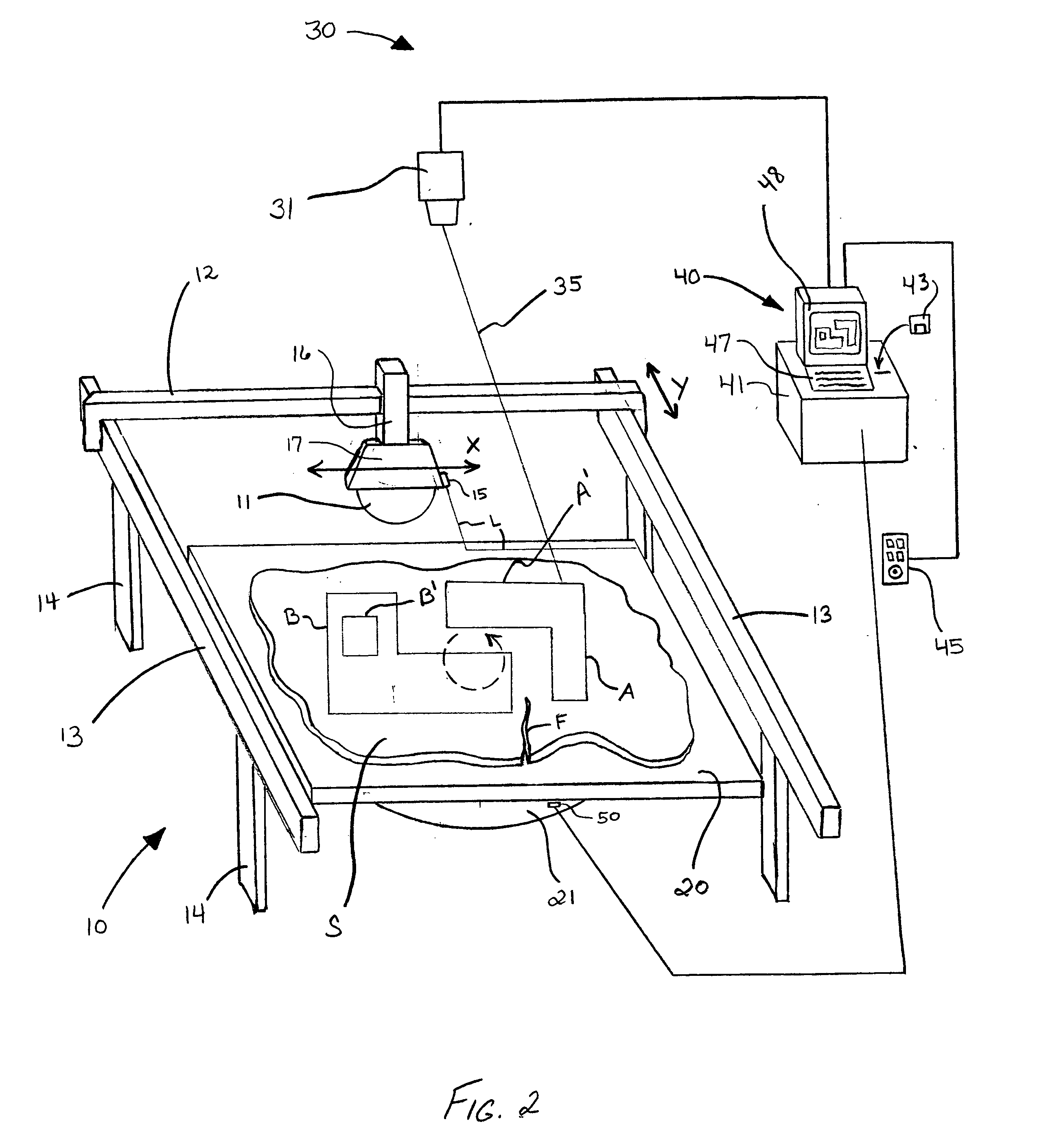
[0033] The present invention is directed to systems and methods for displaying images on a work piece or work surface using, for example, a laser projection system. The present invention also provides systems and methods for processing and / or assembling work pieces using the displayed images as a guide (e.g., as a template). By way of example, the displayed image may comprise a pattern defining the outline of structure to be machined (e.g., cut) from the work piece. While the following detailed description and accompanying drawings depict exemplary embodiments which may be used for cutting stone and similar materials, the scope of the present invention is not so limited.
[0034]FIG. 1 is a schematic illustration of one exemplary embodiment of the present invention. The system of FIG. 1 comprises a work piece processing machine 10, a tool 11 associated with the processing machine for processing the work piece, and an optical projection system 30. Optical projection system 30 includes ...
PUM
| Property | Measurement | Unit |
|---|---|---|
| time | aaaaa | aaaaa |
| shape | aaaaa | aaaaa |
| structure | aaaaa | aaaaa |
Abstract
Description
Claims
Application Information