Mobile/transportable PET radioisotope system with omnidirectional self-shielding

a radioisotope and self-shielding technology, applied in the field of positron emission tomography, can solve the problems of inability to afford the installation of a pet radioisotope production system, the inability to use a scanning site, and the large space occupied by a building structure, etc., to achieve the effect of wide and economic distribution and easy attainable pet radioisotope production capabilities

Inactive Publication Date: 2006-01-26
ACCSYS TECH
View PDF21 Cites 14 Cited by
  • Summary
  • Abstract
  • Description
  • Claims
  • Application Information

AI Technical Summary

Benefits of technology

[0002] This invention pertains to Positron Emission Tomography (PET), and more particularly to a unique, compact, self-shielding system for PET radioisotope production, and to the special form factor, or configuration, per se of such a system. PET radioisotopes play a widely recognized, growingly significant role in modem radiation therapies, and the present invention offers an appreciable new opportunity for making these therapies more widely accessible and available through enabling a more readily attainable, wide and economic distribution of PET radioisotope production capabilities.

Problems solved by technology

Such shielding structure is not part of the shielded device per se, but rather occupies, typically, considerable and costly space in a building structure.
Given this prior art condition, it is also the case that installation of a PET radioisotope production system cannot be afforded in many areas where it might be useful and important, particularly because of the fact that the conventional approach to providing adequate shielding for such a system involves the constructing of a fairly robust and elaborate building structure with a room, or rooms, especially designed for radiation shielding.
Many facilities are now using mobile PET scanners in order to bring PET imaging techniques to remote areas, but they can practically only do these kinds of scans relatively near a site where an accelerator is located to produce the required PET radioisotopes.
Because of the short half-lives of the desired isotopes, transportation times between production sites and use (scanning) sites must be extremely short, and this, as a practical matter, requires that production facilities be located physically quite close to use facilities.
With longer distances between production and use sites, transportation costs simply become prohibitively high, and as a consequence, relatively remote, rural areas do not have ready access to this technology.

Method used


Image

  • Mobile/transportable PET radioisotope system with omnidirectional self-shielding
  • Mobile/transportable PET radioisotope system with omnidirectional self-shielding
  • Mobile/transportable PET radioisotope system with omnidirectional self-shielding

Examples


Embodiment Construction

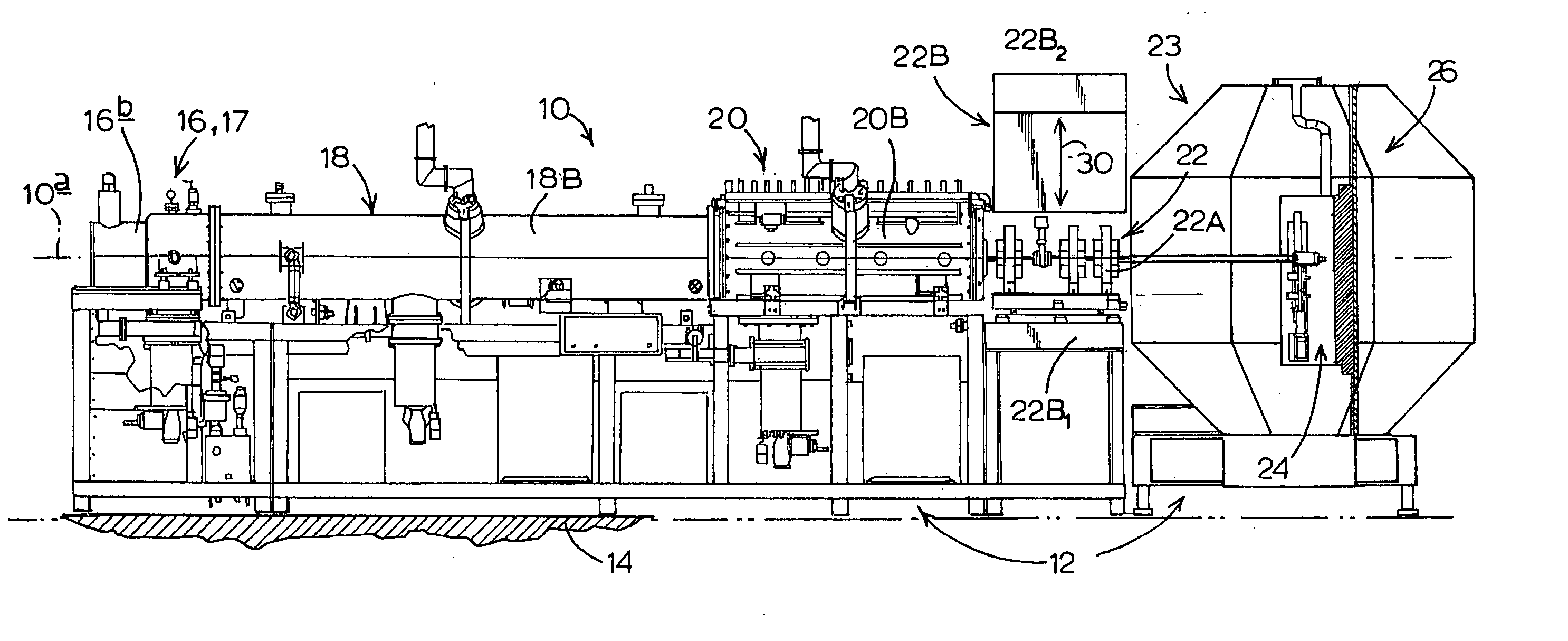
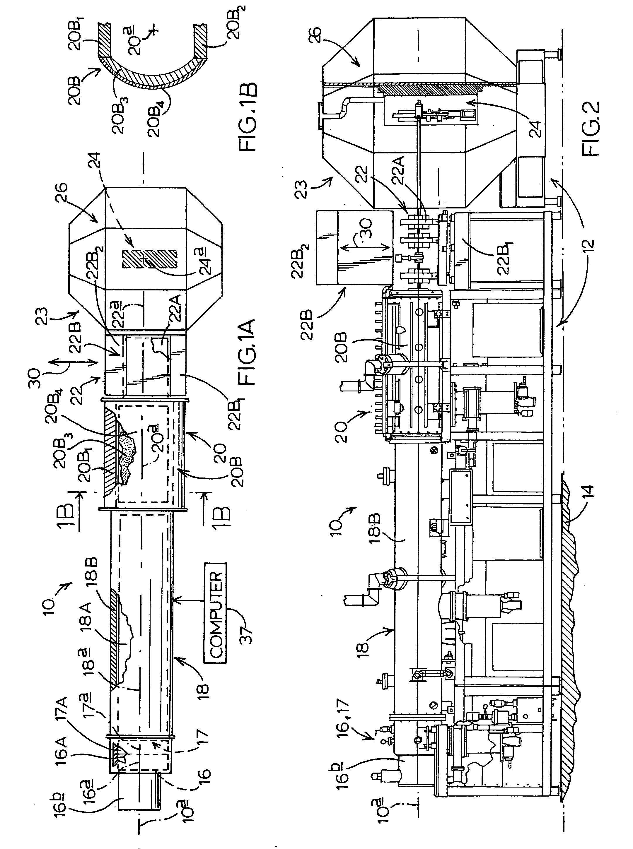
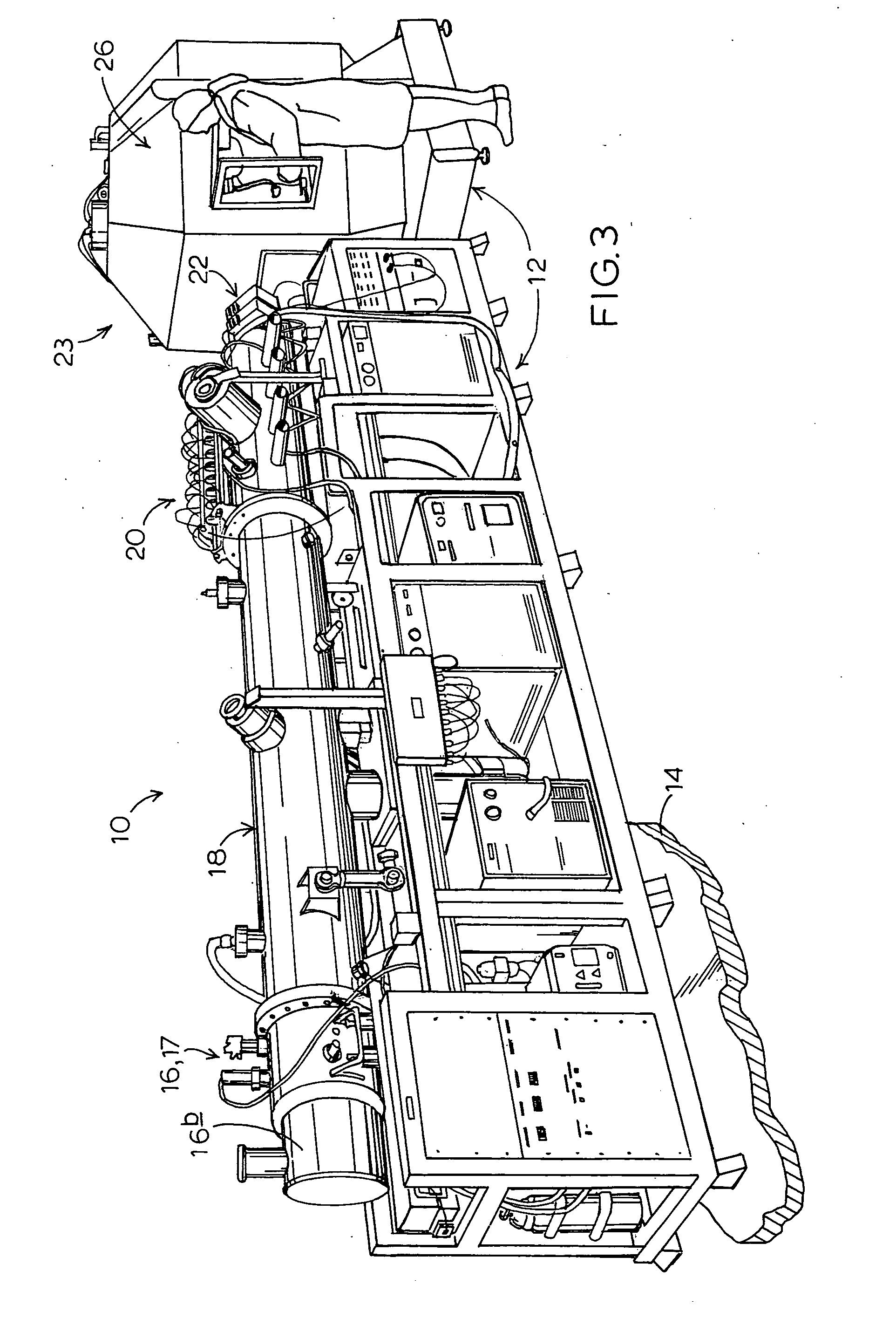
[0028] Turning attention now to the drawings, and referring first of all more particularly to FIGS. 1-3, inclusive, indicated generally at 10 is a PET radioisotope production system, also referred to herein both as a defined-configuration system for PET radioisotope production constructed and as a beam-generation-to-target structure. System 10 operates in accordance with the preferred and best-mode embodiment of the present invention. In FIG. 1 the basic, or core, components of system 10 are illustrated in what can be thought of as being an isolated, though unified, fashion—that is to say, without showing any underlying support framework. FIGS. 2 and 3, however, show this very same system in slightly greater detail, with FIG. 3 picturing an actual test insulation of the system of the invention, where the same core components are illustrated supported through an elongate, distributed framework 12 which is shown resting on a support floor 14 of any suitable nature.

[0029] Important to...


PUM


Abstract

A linear accelerator system for producing PET radioisotopes, and taking the form of a beam-generation-to-target structure which includes form-fitting, self-contained, omnidirectional radiation shielding structure.

Description

CROSS REFERENCE TO RELATED APPLICATION [0001] This application claims priority to U.S. Provisional Patent Application Ser. No. 60 / 581,012, filed Jun. 17, 2004, for “Mobile / Transportable PET Radioisotope System with Omnidirectional Self-Shielding”. The entire content of that prior-filed, currently copending U.S. provisional application is hereby incorporated herein by reference. BACKGROUND AND SUMMARY OF THE INVENTION [0002] This invention pertains to Positron Emission Tomography (PET), and more particularly to a unique, compact, self-shielding system for PET radioisotope production, and to the special form factor, or configuration, per se of such a system. PET radioisotopes play a widely recognized, growingly significant role in modem radiation therapies, and the present invention offers an appreciable new opportunity for making these therapies more widely accessible and available through enabling a more readily attainable, wide and economic distribution of PET radioisotope producti...

Claims


Application Information

Patent Timeline
Patent Type & Authority Applications(United States)
IPC IPC(8): H05H9/00
CPCH05H9/00G21G1/00
Inventor HAMM, ROBERT W.
Owner ACCSYS TECH
Why Eureka
Try Eureka