Exposure system

Inactive Publication Date: 2006-01-26
FUJIFILM CORP +1
View PDF1 Cites 4 Cited by
  • Summary
  • Abstract
  • Description
  • Claims
  • Application Information

AI Technical Summary

Benefits of technology

[0012] In view of the foregoing observations and description, an aspect of the present invention is to provide an exposure system which can prevent the shift in color balance and is long in service life.
[0016] When there is a difference in time constant of deterioration between the plurality of kinds of the light emitting element arrays due to difference in element structure, it is possible to equalize the light emitting element arrays in time constant of deterioration by changing the number N of layers of the superposed light emitting structures of the light emitting elements in the light emitting element arrays. If so, the intensity ratio of light in the respective wavelength ranges can be held constant even after a plurality of repeated exposures and shift of color balance can be prevented.
[0017] The same exposure can be obtained even if the light emitting brightness of one light emitting structure is 1 / S by increasing the light emitting area of the light emitting element to S times. In accordance with the second exposure system of the present invention, the light emitting area of the light emitting element is nonuniform between at least two kinds of light emitting element arrays. Accordingly, when there is a difference in time constant of deterioration between the plurality of kinds of the light emitting element arrays due to difference in element structure, it is possible to equalize the light emitting element arrays in time constant of deterioration by changing the area S of the light emitting elements in the light emitting element arrays. If so, the intensity ratio of light in the respective wavelength ranges can be held constant even after a plurality of repeated exposures and shift of color balance can be prevented.

Problems solved by technology

However, in the exposure system where a color photosensitive material is exposed to light by the use of a plurality of kinds of light emitting element arrays emitting light in different wavelength ranges, e.g., red, green and blue light, there has been a problem that the intensity ratio of light in the respective wavelength ranges fluctuate after a plurality of repeated exposures and color balance is shifted.
However this approach is disadvantageous in that the service life of the exposure system is governed by the service life of the light emitting element array which deteriorates at the highest speed in the parts of the exposure system.
Though problems in the exposure systems using arrays of self-luminous light emitting elements such as an organic EL element has been described, a similar problem can naturally arise in an exposure head using arrays of elements comprising a combination of a dimmer such as a liquid crystal or a PLZT and a light source.

Method used


Image

  • Exposure system
  • Exposure system
  • Exposure system

Examples


first embodiment

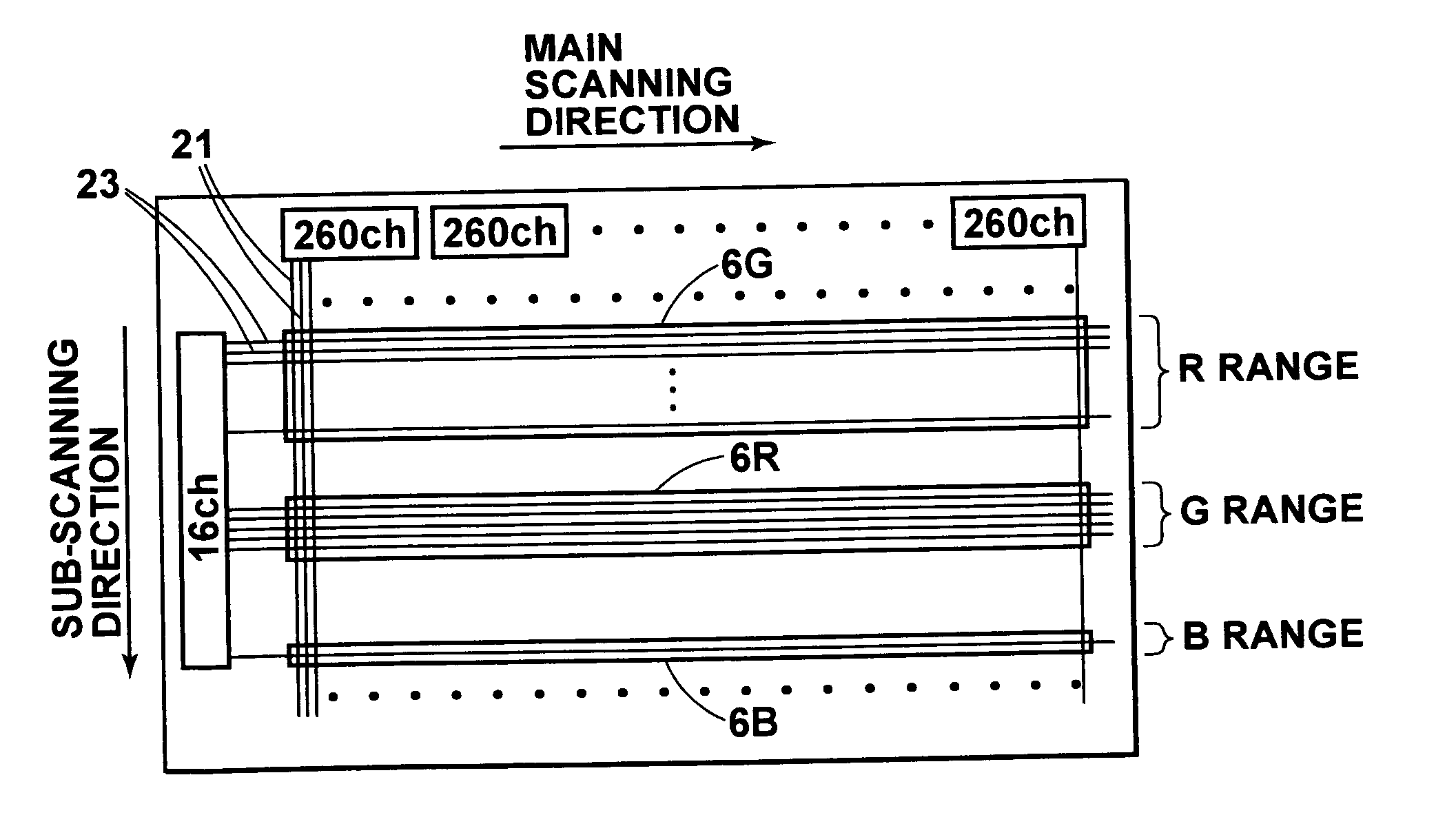
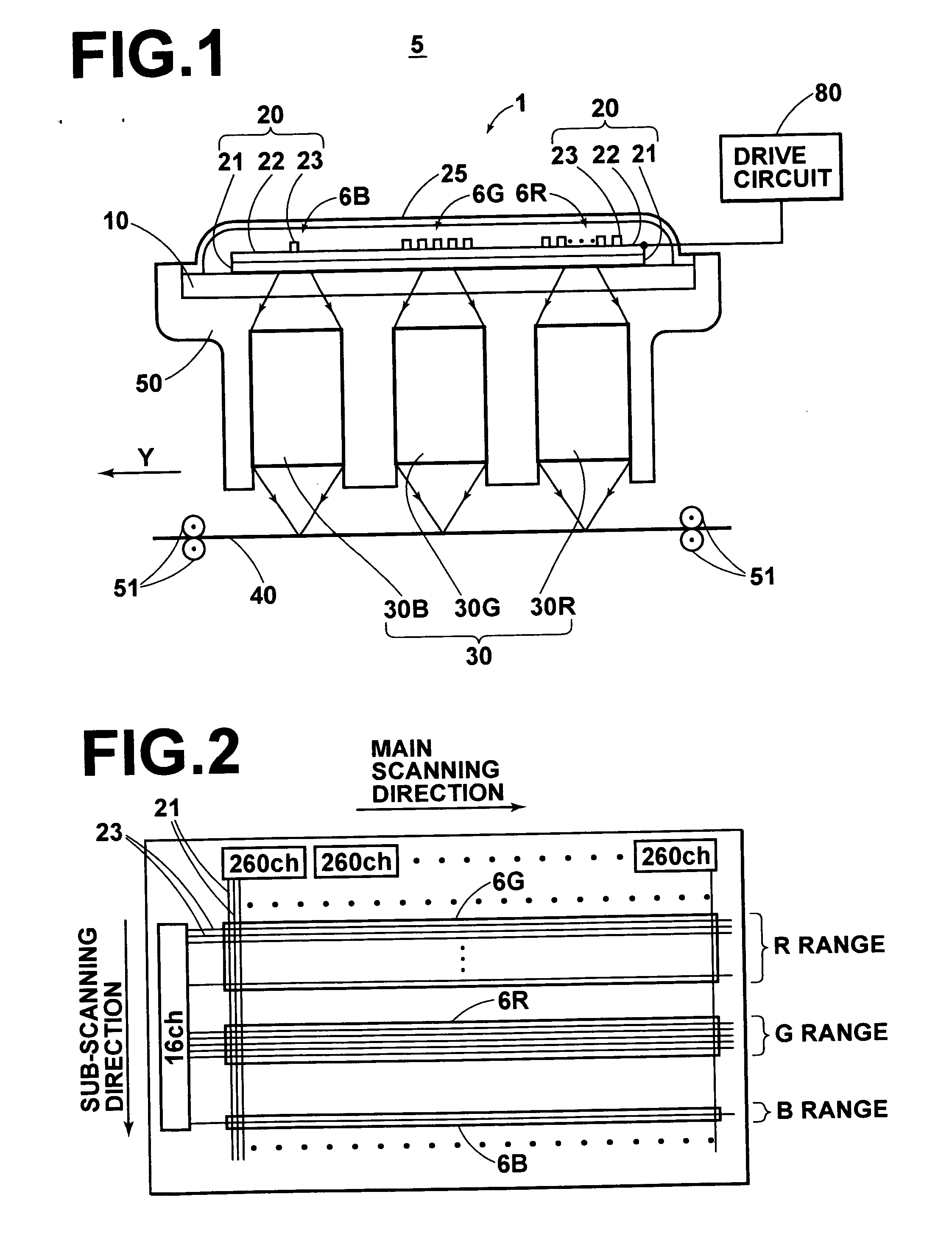
[0023] As shown in FIG. 1, an exposure system 5 in accordance with a first embodiment of the present invention has an exposure head 1. The exposure head 1 comprises a transparent base 10, a red emitting element array 6R, a green emitting element array 6G and blue emitting element arrays 6B formed of number of organic EL elements 20 formed on the base 10 by deposition, refractive index profile type lens arrays 30 (30R, 30G and 30B) which are a unit system for imaging on a color photosensitive material 40 an image generated by the light emitted from the organic EL elements 20, and a support 50 which supports the base 10 and the refractive index profile type lens arrays 30.

[0024] The exposure system 5 further comprises, in addition to the exposure head 1, a sub-scanning means 51 in the form of, for instance, a pair of nip rollers which conveys the color photosensitive material 40 at a constant speed in a direction of arrow Y.

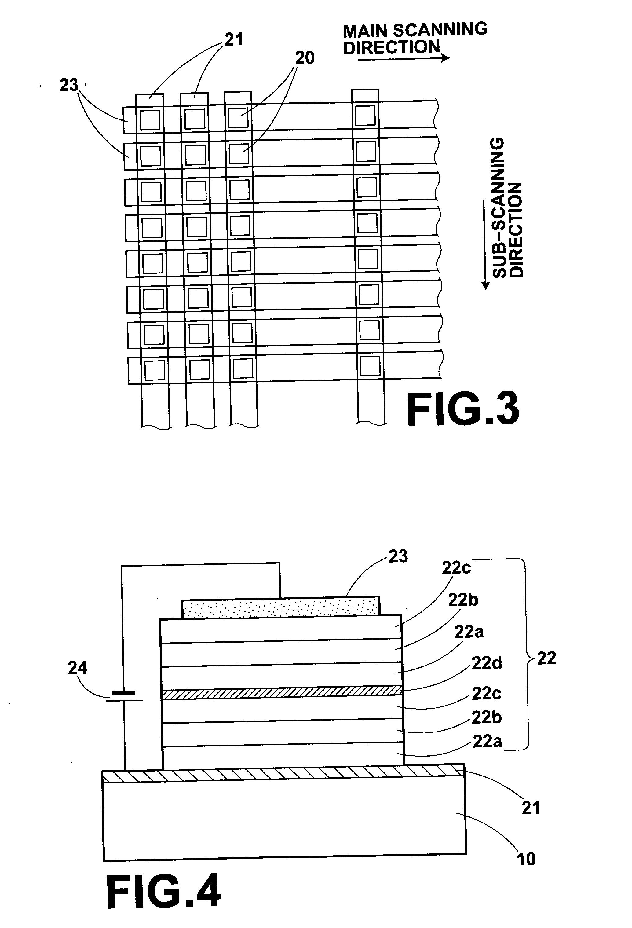
[0025] The organic EL elements 20 comprises an organic comp...

second embodiment

[0056] An exposure system in accordance with a second embodiment of the present invention will be described, hereinbelow. The second embodiment is basically the same as the first embodiment except that the light emitting size of the organic EL element 20B differs from that in the first embodiment. That is, in this embodiment, the organic EL elements 20R, the organic EL elements 20G, and the organic EL elements 20B are all 40×40 μm in light emitting size. Accordingly, the light emitting areas Sr, Sg and Sb are as follows.

Sr=1600 μm2

Sg=1600 μm2

Sb=1600 μm2

[0057] The values of M×N×τ×S for the respective colors are as follows.

Mr×Nr×τr×Sr=9600000 (h·μm2)

Mg×Ng×τg×Sg=9600000 (h·μm2)

Mb×Nb×τb×Sb=10240000 (h·μm2)

[0058] Though the value of Mb×Nb×τb×Sb differs from the value of Mr×Nr×τr×Sr or Mg×Ng×τg×Sg, such a small difference is able to prevent color balance in the exposed image from being largely shifted. Generally, when the ratio of the values of M×N×τ×S of the colors is in about 1:2, it is...

third embodiment

[0061] An exposure system in accordance with a third embodiment of the present invention will be described, hereinbelow. The third embodiment is basically the same as the first embodiment except that the values of M, N, τ and S differ from those in the first embodiment.

[0062] The values in the third embodiment are shown in the following table 3.

TABLE 3MNτ (h)S (μm2)M × N ×τ× S (h ·μm2)R51210016009600000G10320016009600000B11320030009600000

[0063] In this embodiment, since the values of M×N×τ×S for the respective colors are the same as in the first embodiment, it is possible to strictly prevent color balance in the exposed image from being shifted.


PUM


Abstract

An exposure system includes a plurality of kinds of light emitting element arrays, each formed of a plurality of light emitting elements which are arranged in one row in one direction, which are arranged substantially normal to said one direction and emits light in different wavelength ranges, and a sub-scanning mechanism which holds a color photosensitive material in a position where the light from each of the light emitting element arrays is projected, and moves the color photosensitive material and the light emitting element arrays relatively to each other in the one direction. In the exposure system at least one of the plurality of kinds of light emitting element arrays is a multi-layered type light emitting element array or the light emitting area of the light emitting element is nonuniform between at least two kinds of light emitting element arrays.

Description

BACKGROUND OF THE INVENTION [0001] 1. Field of the Invention [0002] This invention relates to an exposure system, and more particularly to an exposure system for exposing a color photosensitive material by the use of a plurality of kinds of light emitting element arrays emitting light in different wavelength ranges. [0003] 2. Description of the Related Art [0004] As disclosed, for instance, in U.S. Pat. No. 6,731,322 and Japanese Unexamined Patent Publication No. 2001-260416, there has been known a system where a color photosensitive material is exposed to light by the use of an exposure head comprising a plurality of kinds of light emitting element arrays emitting light in different wavelength ranges, e.g., red, green and blue light. [0005] Each of the light emitting element arrays generally comprises a plurality of organic EL (electroluminescence) elements which are arranged in one or more rows and emits light in the same wavelength range, and in the exposure head, a plurality of ...

Claims


Application Information

Patent Timeline
IPC IPC(8): B41J2/45
CPCB41J2/451
Inventor HYUGA, HIROAKI
Owner FUJIFILM CORP
Why Eureka
Try Eureka