

Paper feeding mechanism for continuous form printer
- Summary
- Abstract
- Description
- Claims
- Application Information
AI Technical Summary
Benefits of technology
Problems solved by technology
Method used
Image

Examples
Embodiment Construction
[0031] Referring to the drawings, an embodiment according to the present invention will be described hereinafter.
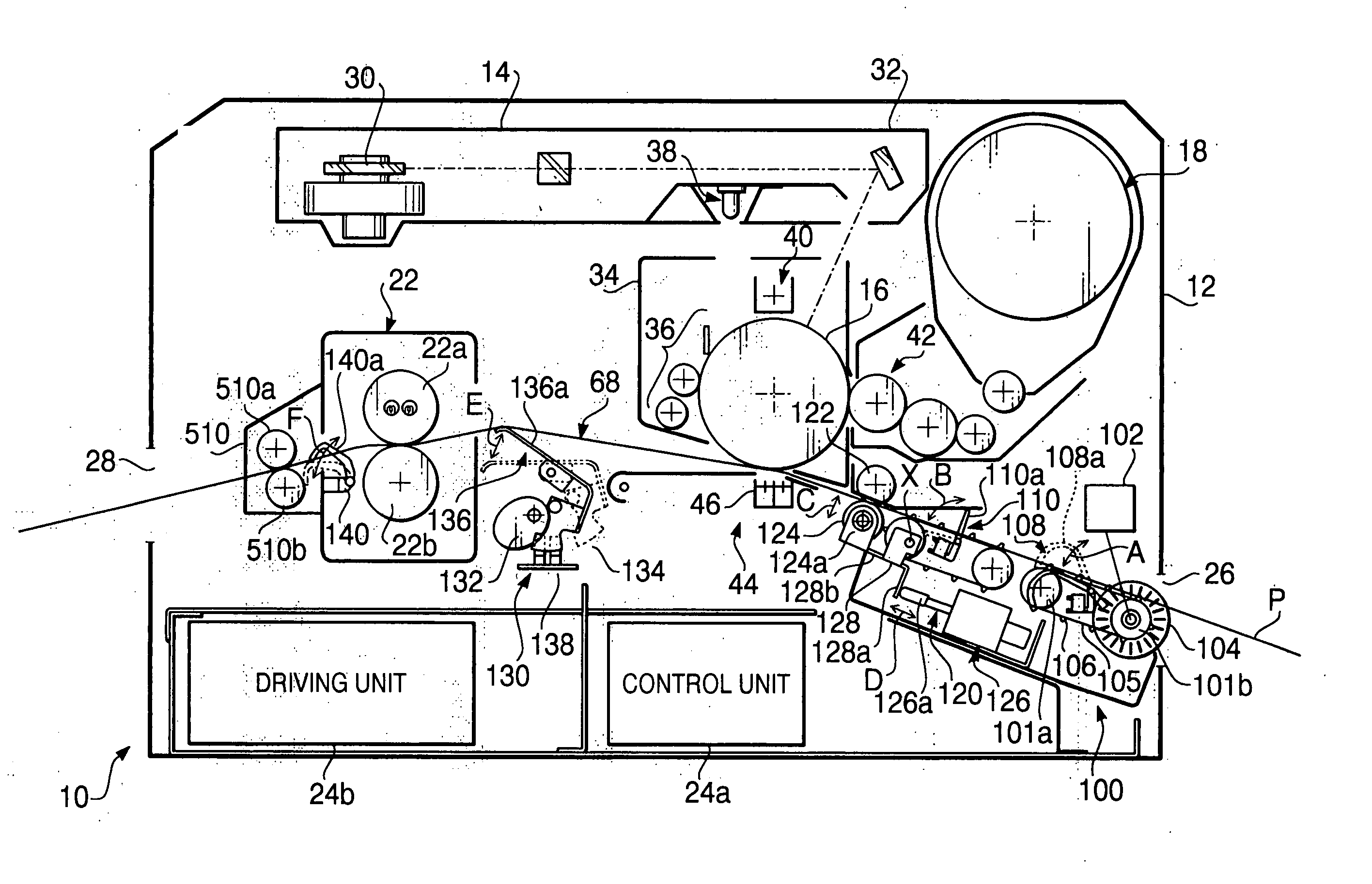
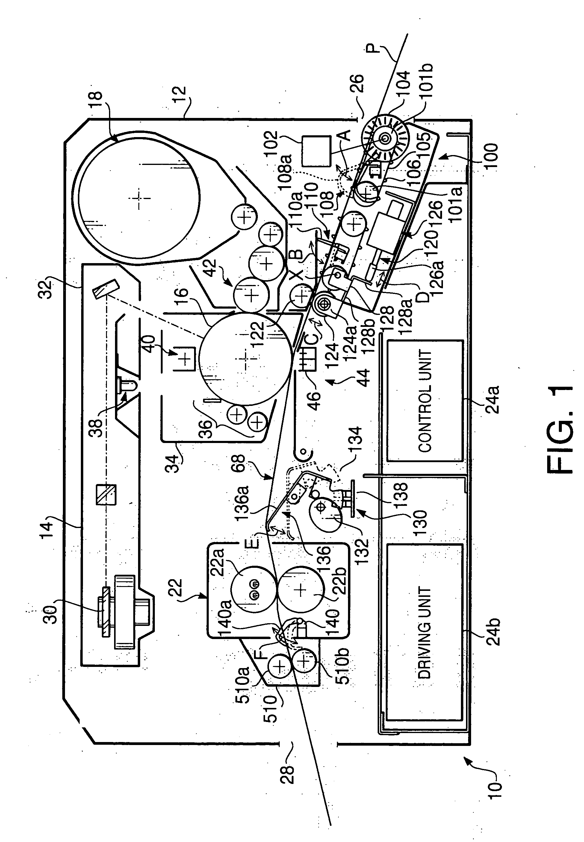
[0032]FIG. 1 is a sectional side view schematically showing a structure of a continuous form printer 10 according to the embodiment. The printer 10 is an electrophotographic printer, which prints images and / or characters on continuous form paper P, as fanfold paper, in accordance with the electrophotographic Imaging process using a laser beam. In this embodiment, the images and / or characters to be printed are transferred from an external device such as a computer device in the form of print data.
[0033] The continuous form paper P has sprocket holes h (see FIG. 4) at a predetermined pitch on either side, in the width direction, of the paper P. The pitch of the sprocket holes h is {fraction (1 / 2)} inches in this embodiment, however other fanfold paper having different pitch of sprocket holes can be used. Furthermore, the continuous form paper P has separation perforations...
PUM
 Abstract
Description
Claims
Application Information