Liquid crystal display

Inactive Publication Date: 2006-01-26
TOSHIBA MATSUSHITA DISPLAY TECH
View PDF15 Cites 37 Cited by
  • Summary
  • Abstract
  • Description
  • Claims
  • Application Information

AI Technical Summary

Benefits of technology

[0023] According to the third aspect, the reflective electrode of the LCD is arranged on the liquid crystal layer side of the color filter, so that no external light is transmitted through the color filter under the reflective electrode, to thereby realize monochromatic reflective display.
[0024] In this way, the LCD according to the present invention includes the array substrate having the detective elements to detect an object presented in front of the array substrate. The counter electrode of the LCD includes the color filter to transmit light emitted from the light source, the transparent electrode that faces th

Problems solved by technology

Simply combining the structures of the two types of LCD by forming detective elements and reflective electrodes on an array substrate is unsatisfactory becaus

Method used


Image

  • Liquid crystal display
  • Liquid crystal display
  • Liquid crystal display

Examples


Embodiment Construction

[0030] A liquid crystal display (LCD) according to an embodiment of the present invention will be explained.

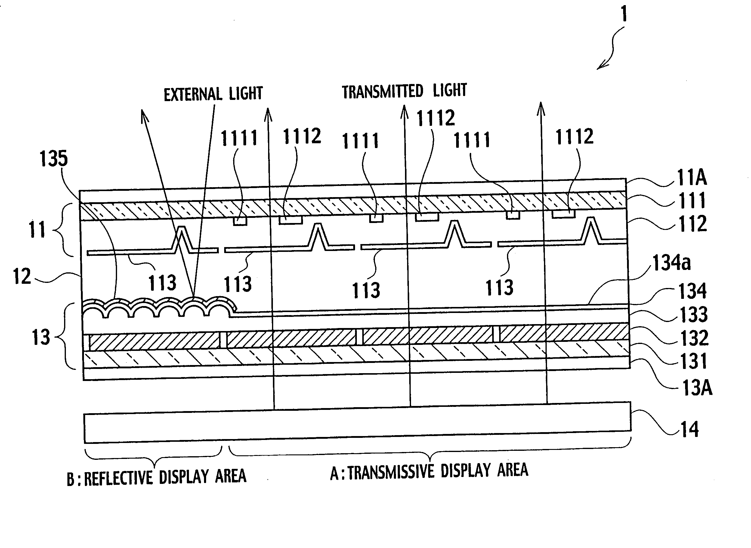
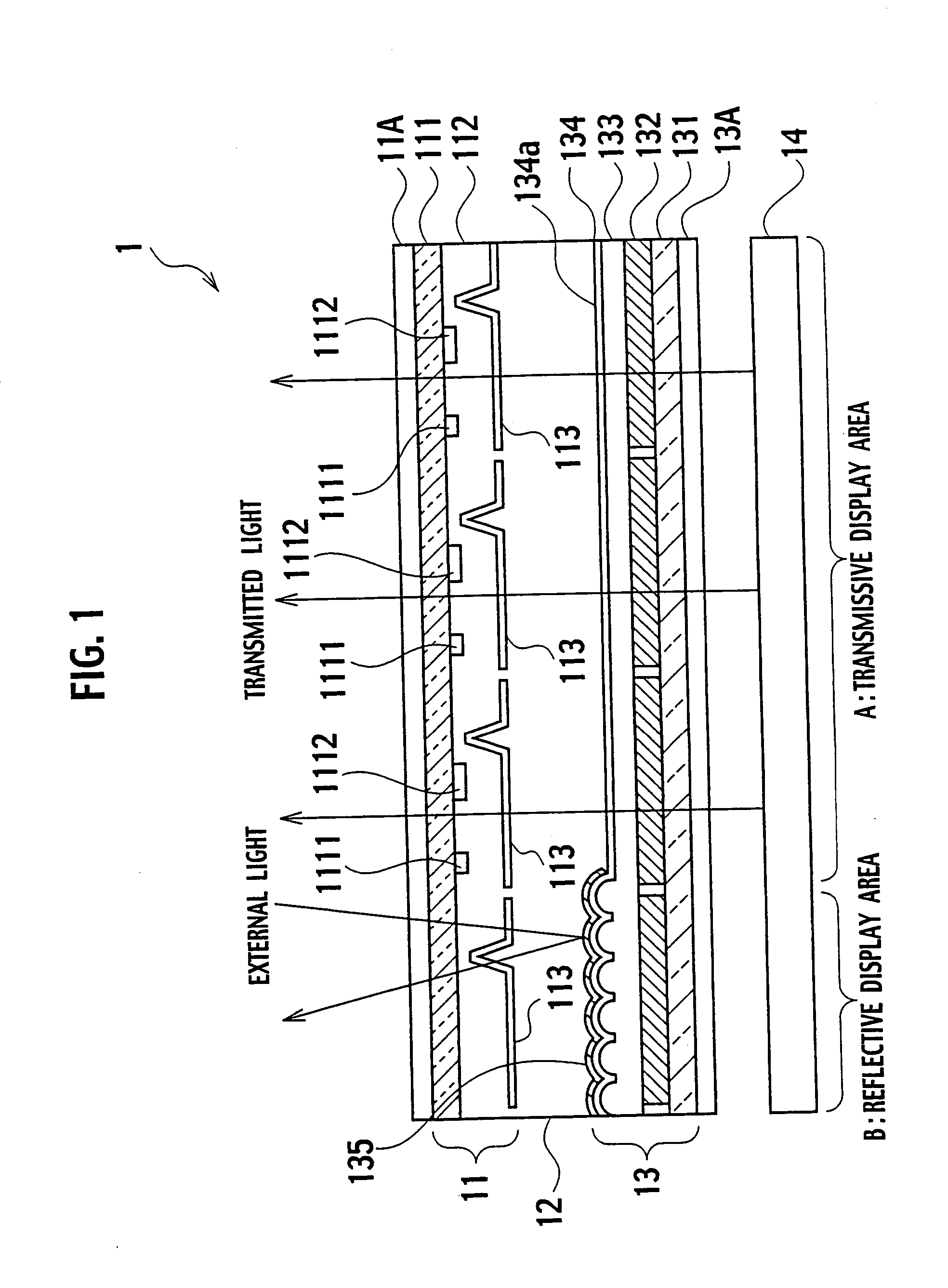
[0031]FIG. 1 is a sectional view partly showing the LCD 1 according to an embodiment of the present invention.

[0032] The LCD 1 has an array substrate 11 on which a plurality of scanning lines (not shown) and a plurality of signal lines (not shown) are formed. The scanning lines and the signal lines cross each other. The array substrate 11 faces a counter substrate 13, and a liquid crystal layer 12 is held between the array substrate 11 and the counter substrate 13.

[0033] In the LCD 1, red (R), green (G), and blue (B) pixels are regularly arranged at crossing portions of the scanning lines and the signal lines, respectively. An image displayed with the pixels is viewed in front of the array substrate 11. Behind the counter substrate 13, there is a surface light source 14.

[0034] The number of the signal lines is, for example, 240 for each of the R, G, and B colors. The numbe...


PUM


Abstract

A liquid crystal display (1) includes an array substrate (11), a liquid crystal layer (12), and a counter substrate (13). The array substrate has optical sensors (1112) to detect light from an object presented in front of the array substrate. The counter electrode has a color filter (132) to transmit light emitted from a light source (14), a transparent electrode (134a) that faces a first plurality of pixel electrodes (113) and transmits the light transmitted through the color filter, and a reflective electrode (135) that faces a second plurality of pixel electrodes (113) and reflects external light. The light from the object to be detected is directly given to the optical sensors, which can therefore correctly detect the object. The light emitted from the light source and transmitted through the transparent electrode and the external light reflected from the reflective electrode realize transmissive display and reflective display.

Description

CROSS-REFERENCE TO RELATED APPLICATION [0001] This application is based upon and claims the benefit of priority from the prior Japanese Patent Application No. 2004-213268, filed on Jul. 21, 2004. The entire contents of which are incorporated herein by reference. BACKGROUND OF THE INVENTION [0002] 1. Field of the Invention [0003] The present invention relates to a liquid crystal display capable of correctly detecting an object and conducting transmissive display as well as reflective display. [0004] 2. Description of Related Art [0005] Liquid crystal displays (LCDs) are thin, lightweight, and low in power consumption, and therefore, are widely used for cellular phones, smart-phones, PDAs (personal digital assistants), personal computers, and the like. [0006] The LCD has an array substrate on which scanning lines and signal lines cross each other, a counter substrate, a liquid crystal layer held between the array substrate and the counter substrate, and a drive circuit for driving the...

Claims


Application Information

Patent Timeline
IPC IPC(8): G02F1/1335
CPCG02F1/13338G02F1/133555G02F2001/13312G02F1/1368G02F1/136227G02F1/13312
Inventor MORIMOTO, HIROKAZUKINOSHITA, MASAKI
Owner TOSHIBA MATSUSHITA DISPLAY TECH
Why Eureka
Try Eureka