
System and method for inspecting railroad track

a technology for inspecting systems and railroad tracks, applied in distance measurement, transportation and packaging, instruments, etc., can solve the problems of time-consuming visual inspection process, cross-ties to deteriorate, and inconvenient inspection of these aspects of rails,

Active Publication Date: 2006-01-26
LORAM TECH INC
View PDF23 Cites 126 Cited by
  • Summary
  • Abstract
  • Description
  • Claims
  • Application Information

AI Technical Summary

Benefits of technology

[0009] The foregoing summary is not intended to summarize each potential embodiment or every aspect of the subject matter of the present disclosure.

Problems solved by technology

Over time, environmental factors can cause the crossties to deteriorate until they must be replaced.
The process of visual inspection is quite time consuming.
As with the grading of crossties, inspecting these aspects of rail can also be time consuming.

Method used


Image

  • System and method for inspecting railroad track
  • System and method for inspecting railroad track
  • System and method for inspecting railroad track

Examples


Embodiment Construction

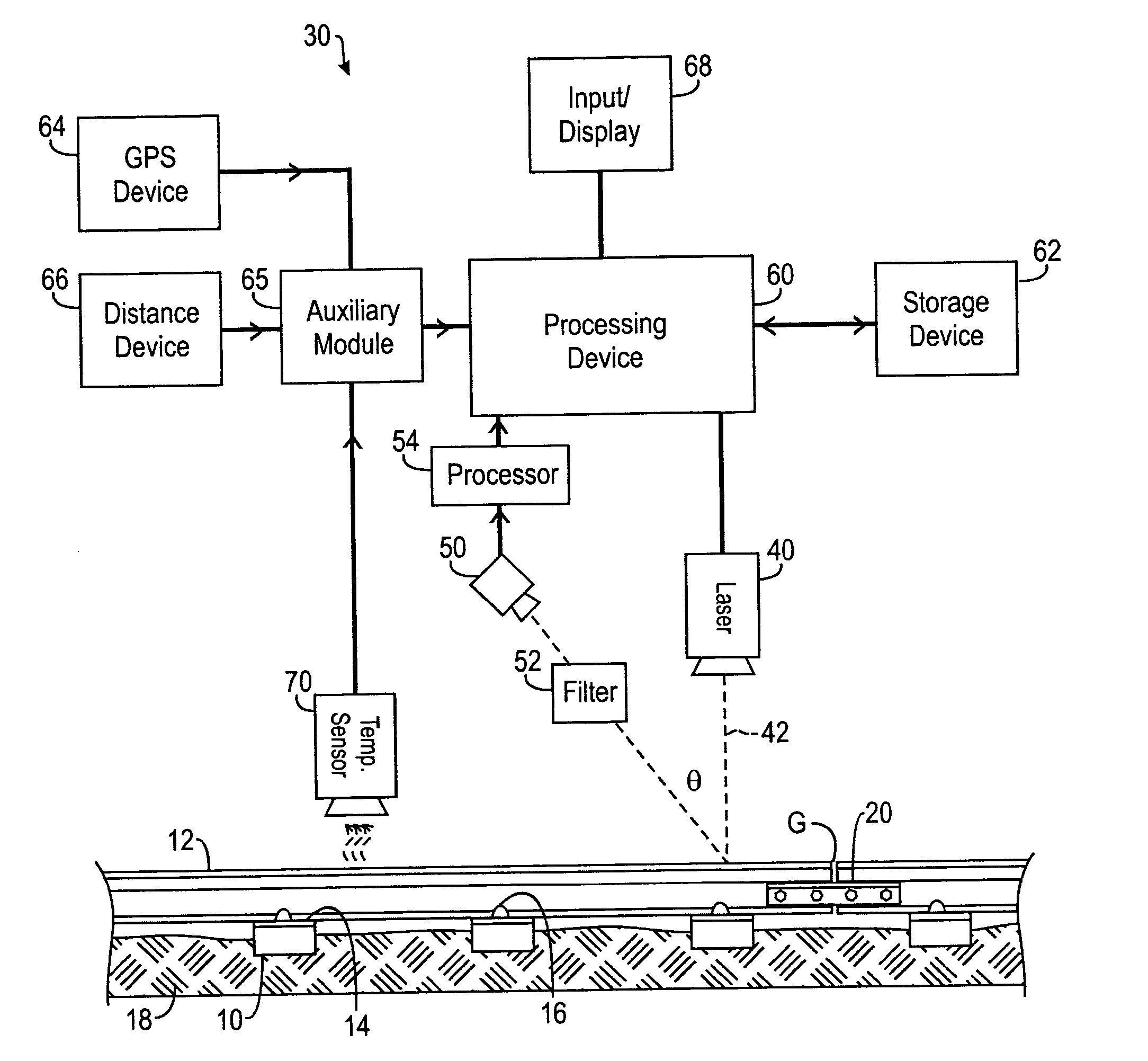
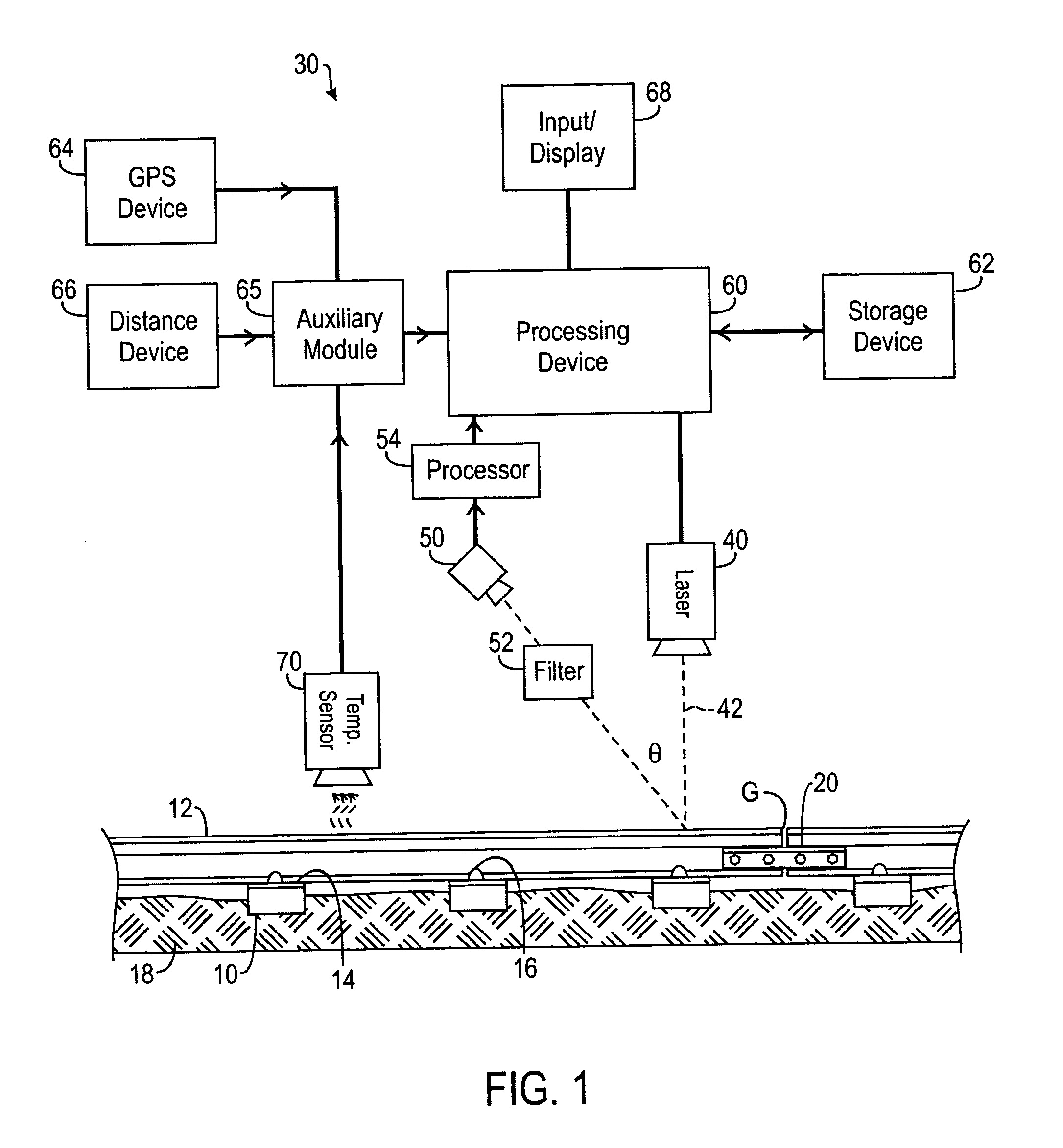
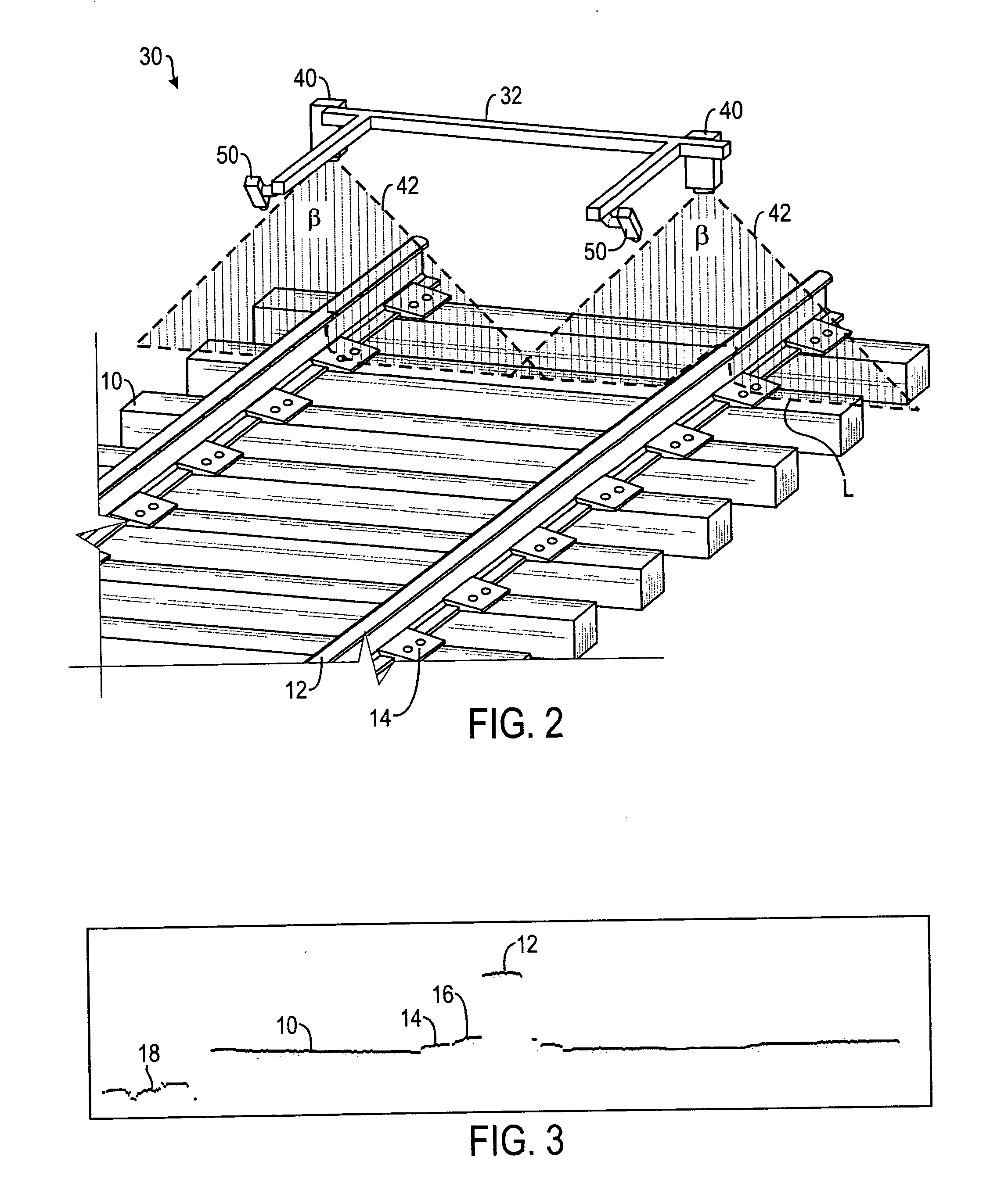
[0023] Referring to FIGS. 1 and 2, an embodiment of a system 30 for inspecting railroad track according to certain teachings of the present disclosure is illustrated. In FIG. 1, the disclosed inspection system 30 is schematically illustrated relative to a railroad track. In FIG. 2, a portion of the disclosed inspection system 30 is illustrated in a perspective view relative to railroad track.

[0024] As best shown in FIG. 1, the disclosed inspection system 30 includes a light generator such as a laser 40, a device for receiving light reflected from the area to be inspected such as a camera 50, and a processing device 60. In the implementation shown in FIG. 1, the disclosed inspection system 30 is used to survey the track bed of a railroad track. Although the disclosed inspection system and associated methods are described for use in inspecting railroad track, it will be appreciated with the benefit of the present disclosure that the disclosed system and method can be used in other ar...


PUM


Abstract

A system and method for inspecting railroad track is disclosed. The disclosed system includes lasers, cameras, and a processor. The lasers are positioned adjacent the track. The laser emits a beam of light across the railroad track, and the camera captures images of the railroad track having the beam of light emitted thereon. The processor formats the images so that they can be analyzed to determine various measurable aspects of the railroad track. The disclosed system can include a GPS receiver or a distance device for determining location data. The measurable aspects that can be determined by the disclosed system include but are not limited to the spacing between crossties, the angle of ties with respect to rail, cracks and defects in surface of ties, missing fastener components, misaligned fastener components, sunken tie plates, raised spikes, rail wear, gage of rail, ballast height relative to ties, size of ballast stones, and break or separation in the rail. The system includes one or more algorithms for determining these measurable aspects of the railroad track.

Description

CROSS REFERENCE TO RELATED APPLICATION [0001] This application is a non-provisional application claiming priority to U.S. Provisional Application Ser. No. 60 / 584,769, entitled, “System and Method for Inspecting Railroad Track,” by John Nagle and Steven C. Orrell, filed Jun. 30, 2004, hereby incorporated by reference in its entirety herein.FIELD OF THE INVENTION [0002] The present invention relates generally to a system and method for inspecting railroad track and, more particularly to a system and method for inspecting aspects of a railroad track using a laser, camera, and a processor. BACKGROUND OF THE INVENTION [0003] Railroads are generally constructed on a base layer of compacted, crushed stone material. A layer of gravel ballast rests on top of this stone layer. Crossties are laid in and on this ballast layer, and two parallel steel rails are attached to the crossties with fasteners. The majority of crossties in service are made of wood. Various other materials are used such as...

Claims


Application Information

Patent Timeline
Patent Type & Authority Applications(United States)
IPC IPC(8): G01C3/08
CPCB61K9/08G01C3/085G01C3/08B61L23/044B61L23/045
Inventor VILLAR, CHRISTOPHER M.ORRELL, STEVEN C.NAGLE, JOHN ANTHONY II
Owner LORAM TECH INC
Learn More