Stent delivery system allowing controlled release of a stent

a delivery system and stent technology, applied in the field of stent delivery system, can solve problems such as overlap of the stent and interfere with the shoulder

Active Publication Date: 2006-01-26
COOK MEDICAL TECH LLC
View PDF33 Cites 107 Cited by
  • Summary
  • Abstract
  • Description
  • Claims
  • Application Information

AI Technical Summary

Benefits of technology

[0019] Upon deployment of the stent, such trapping of the stent prevents the stent from jumping out of the stent delivery system. The stent remains within the stent delivery syst...

Problems solved by technology

Each rivet overlaps and...

Method used


Image

  • Stent delivery system allowing controlled release of a stent
  • Stent delivery system allowing controlled release of a stent
  • Stent delivery system allowing controlled release of a stent

Examples


first embodiment

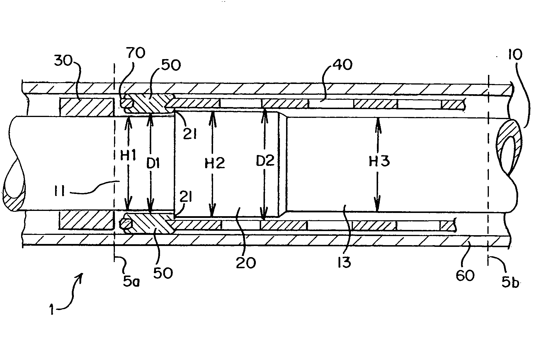
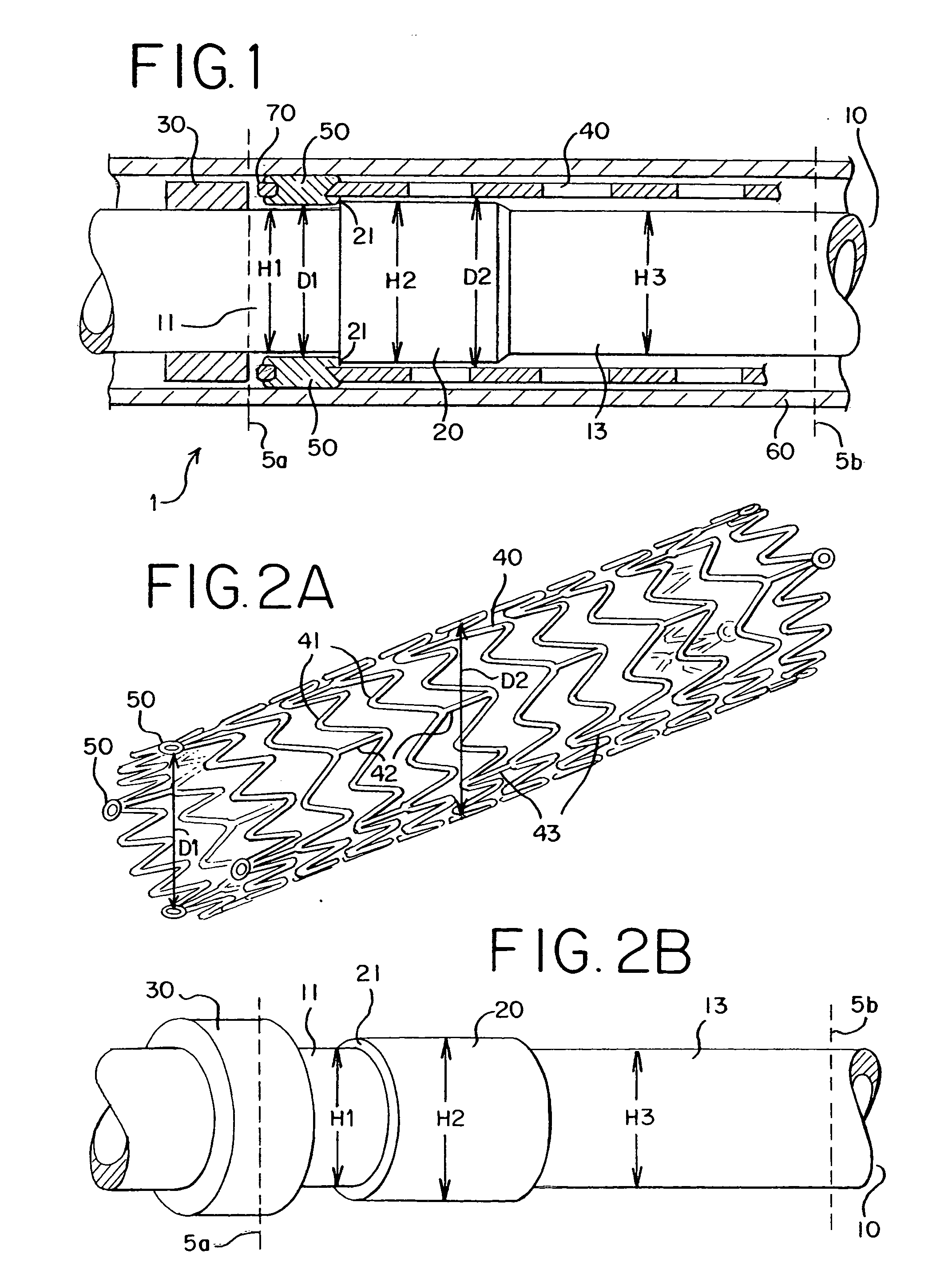
[0030]FIG. 1 shows a stent delivery system 1. The stent delivery system 1 comprises a sheath 60 and a holder 10. The sheath 60 and the holder 10 have a tubular shape and extend from a proximal end 5a to a distal end 5b. A holder band 30 is positioned at the proximal end 5a. A stent 40 is interposed between the sheath 60 and the holder 10. The stent 40 comprises at least one eyelet 70 and at least one rivet 50.

[0031] The sheath 60 applies pressure to the stent 40 so that the stent 40 remains in a collapsed state. The holder band 30 extends radially around the holder 10 as shown in FIGS. 1 and 2B. The holder band 30 may be made of any material but is preferably rigid and hard. The holder band 30 blocks a longitudinal movement of the stent 40 as the sheath 60 is pulled rearward. Thus, the holder band 30 prevents the stent 40 from moving along with the retracted sheath 60.

[0032] Preferably, the stent 40 is in a collapsed state during delivery as shown in FIG. 1. The stent 40 is a self-...

second embodiment

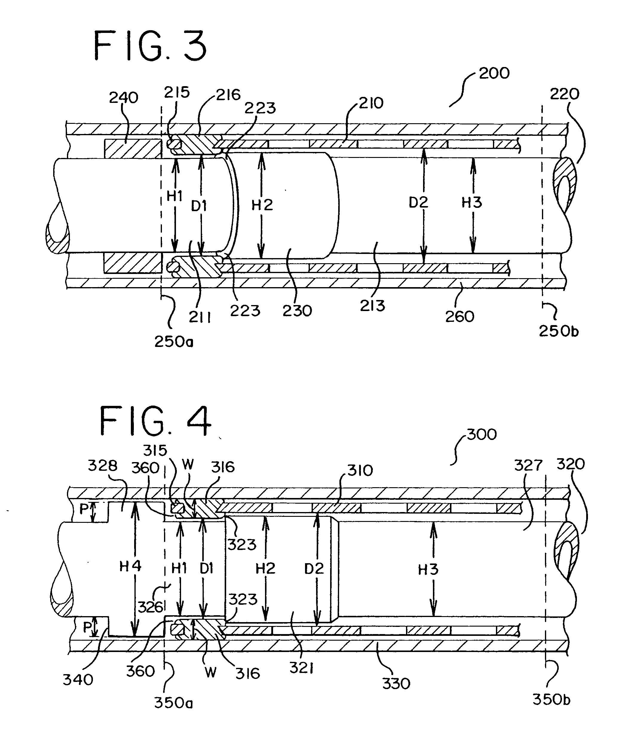
[0046]FIG. 3 shows a stent delivery system 200. The stent delivery system 200 includes a sheath 260, a stent 210 and a holder 220. The stent 210 has a first portion comprising eyelets 215 and rivets 216 attached to the eyelets 215. The first portion has a first inner diameter D1, which is smaller than a second inner diameter D2. The stent 210 has a second portion having the second inner diameter D2 as shown in FIG. 3. The holder 220 comprises a proximal section, i.e., a first section 211, a second section and a distal section, i.e., a third section 213. The first section 211 has a first diameter H1 and the second section has a second diameter H2, which is larger than H1. The third section 213 has a third diameter H3, which is smaller than or the same as the first diameter. The diameters H1, H2 and the inner diameters D1, D2 have small dimensions. A holder band 240 is positioned at a proximal end 250a to block the rearward movement of the stent 210 when the sheath 260 is retracted.

[0...

third embodiment

[0049] a stent delivery system 300 is shown in FIG. 4. The stent delivery system 300 includes a stent 310, a holder 320 and a sheath 330. The holder 320 includes a bump 321 and is designed to make the holder band 340 an integrated part. Accordingly, the holder 320 includes a proximal section, i.e., a first section 326, a second section having the bump 321, a distal section (i.e., a third section 327), and a holder band section (i.e., a fourth section 328), as shown in FIG. 4. The holder band 340 needs to have a distance (P) that is sufficient to receive eyelets 315 of the stent 310. Accordingly, the holder band section 328 has a diameter H4, which is larger than the two diameters H1 and H2, as shown in FIG. 4. As discussed above, the diameters H1 and H2 are about 0.053 and 0.059 inch, respectively. The diameter H4 is about 0.075 inch. Each distance P, as shown in FIG. 4, is typically 0.022 inch per side. The width W of each eyelet 315 is about 0.025˜0.027 inch. The third diameter H3...


PUM


Abstract

A stent delivery system includes a stent having at least one eyelet and at least one rivet and a holder supporting the stent, wherein the holder includes a first section having a first diameter and a second section having a second diameter. A sheath covers the stent and the holder. The rivets are attached to each of the eyelets. A first inner diameter of the stent at the position of the rivets is smaller than a second inner diameter of the stent at other positions because the rivets protrude inwardly. A shoulder is formed on the holder due to the difference between the first diameter and the second diameter of the holder. The shoulder is positioned distally adjacent the rivets. The shoulder interferes with the protruding rivets, thereby restraining the longitudinal movement of the stent relative to the holder. Although the sheath is pulled back, the stent does not jump out of the stent delivery system. As a result, the stent delivery system allows the stent to be released in a controlled manner upon its deployment.

Description

BACKGROUND OF THE INVENTION [0001] 1. Field of Invention [0002] The present invention relates to a stent delivery system. More particularly, the present invention relates to a stent delivery system that allows a stent to be released in a controlled manner upon its deployment. [0003] 2. Description of the Prior Art [0004] Stents are well known and widely used in medical procedures. Stents are frequently used to treat various organs and vessels in the vascular system. In particular, stents are most commonly used to treat vascular diseases using endovascular procedures. Patients who suffer from vascular diseases typically develop stenosis of various arteries, i.e., blood vessels that are clogged or narrowed by substances that restrict blood flow. Traditionally, operations such as bypass surgery have been performed to treat the stenosis of arteries. Bypass surgery involves opening of the chest cavity, which is a very invasive procedure for patients. [0005] The development of fluoroscopy...

Claims


Application Information

Patent Timeline
IPC IPC(8): A61F2/06A61F2/86
CPCA61F2/86A61F2/91A61F2/915A61F2/95A61F2230/0054A61F2002/91575A61F2002/9665A61F2250/0039A61F2220/0041A61F2002/91533
Inventor PARKER, FRED T.
Owner COOK MEDICAL TECH LLC
Why Eureka
Try Eureka