Sensor and method of mounting it

US20060021242A1Active Publication Date: 2006-02-02OPTOLAB LICENSING GMH

Image

  • Sensor and method of mounting it
  • Sensor and method of mounting it
  • Sensor and method of mounting it

Examples


Embodiment Construction

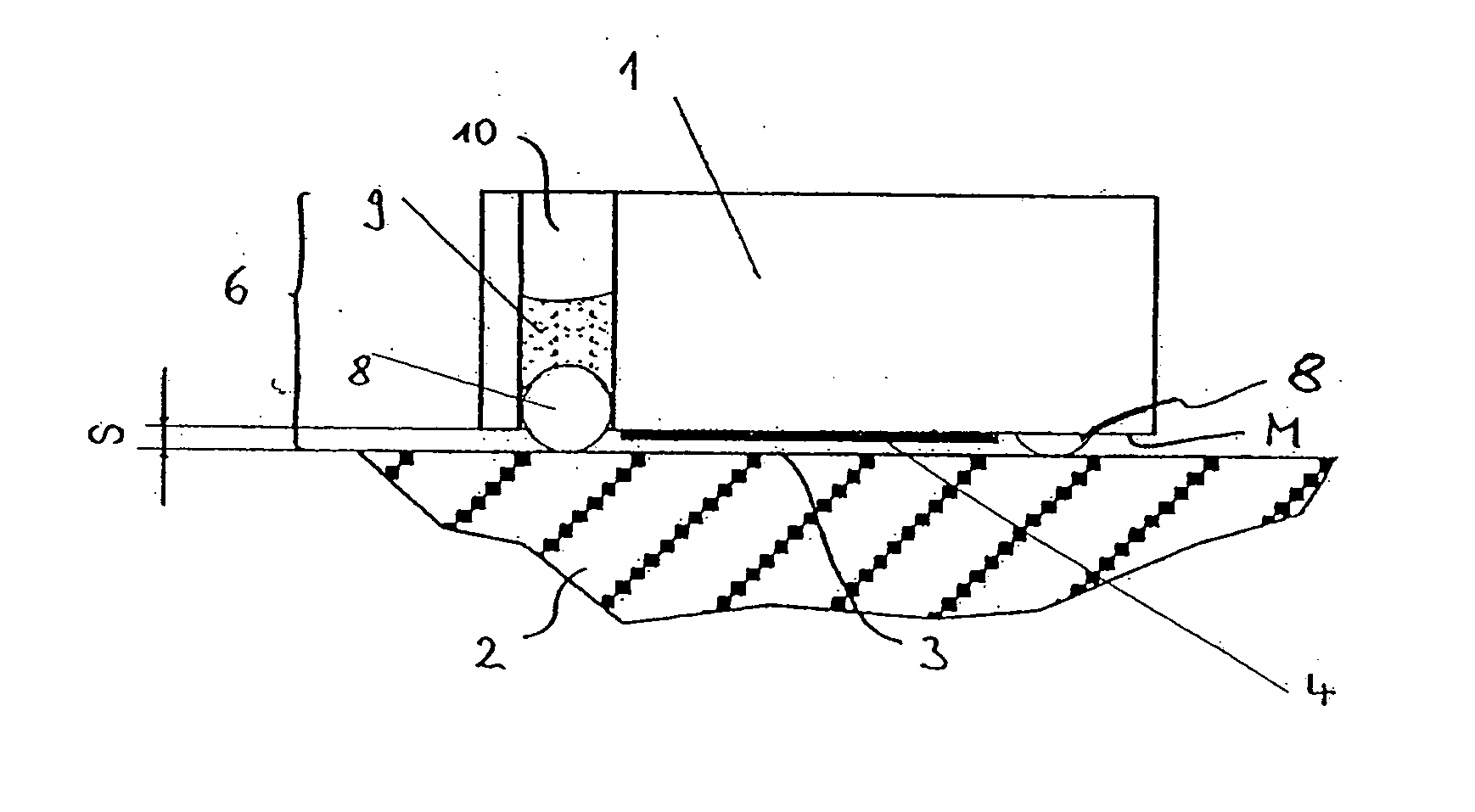
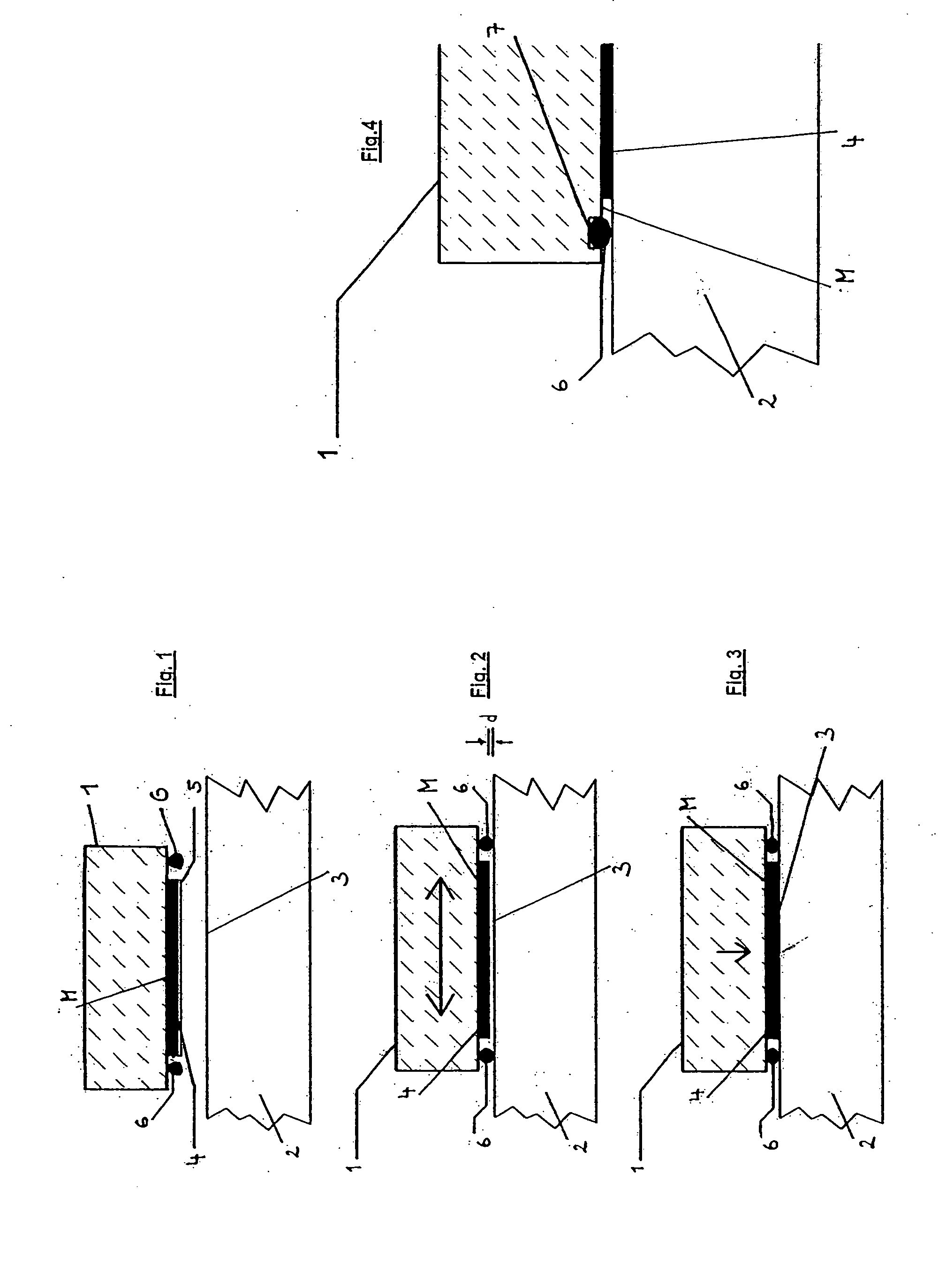
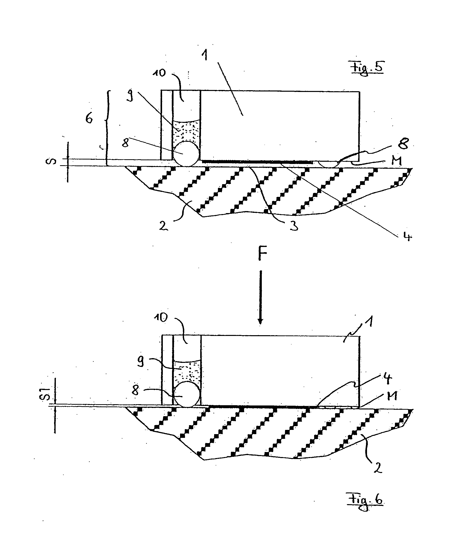
[0040]FIG. 1 shows a schematic sectional view of a sensor element 1, in a phase of the mounting process, before the sensor element 1 is mounted to a part 2. In the embodiment shown, the sensor element 1 is part of a measuring system (not shown in detail), which detects, for example, the movement of one machine part relative to another machine part. However, the sensor element may also be any other structural part which is to be mounted to an attachment surface or an attachment part in a determined position to be adjusted. It is merely essential for the following description that the element 1 be mounted to the part 2, e.g. to an attachment surface thereof, to achieve a position adjusted with high precision. The adjustment may relate to the part 2 or to a third part.

[0041] Mounting of the sensor element 1 to the part 2 is effected by gluing a mounting surface M of the sensor element 1 to the attachment surface 3, e.g. by means of an adhesive bond. For this purpose, an adhesive layer...


PUM


Abstract

What is described is a structural part comprising a mounting surface (M) for mounting the mounting surface to an attachment surface, wherein means for adhesive-bonding the mounting surface (M) with the attachment surface are provided, in order to glue the structural part to the attachment surface, and wherein spacers are provided on the mounting surface (M), said spacers causing a predetermined gap (S) between the mounting surface (M) and the attachment surface when attaching the structural part to the attachment surface and being removable and / or deformable by pressing the structural part onto the attachment surface.

Description

CROSS-REFERENCE TO RELATED APPLICATION FIELD OF THE INVENTION [0001] The invention relates to a structural part comprising a mounting surface for mounting to an attachment surface, with means being provided for adhesive-bonding the mounting surface with the attachment surface, so as to glue said structural part to the attachment surface. The invention further relates to a method of mounting a structural part to an attachment surface, wherein a mounting surface of said structural part is adhesive-bonded to the attachment surface. BACKGROUND OF THE INVENTION [0002] In many cases, structural parts have to be mounted to attachment surfaces in predetermined positions. Adhesive bonds have turned out to be particularly favorable for such mounting, because they are easy to apply, but screw connections or clamped connections are also used. An example of a structural part to be adhesive-bonded is present, for example, in length or angle measuring systems, in which it is very common to glue tr...

Claims


Application Information

Patent Timeline
02 Feb 2006
Publication
US20060021242A1
IPC
A45B3/08
CPC
G01D11/30; G01D5/34707
Inventors
BOGE, LUDWIG; FRANZ, HEINZ-GUNTHER