Harmonic reflective load-pull tuner

a tuner and harmonic reflection technology, applied in the field of harmonic reflective tuner system, can solve the problems of loss of triplexer, reduced performance, and reduced band rejection, so as to achieve the effect of easy manufacturing and good isolation of fundamental tuning from harmonic tuning

Inactive Publication Date: 2006-02-02
BOULERNE PHILIPPE
View PDF2 Cites 6 Cited by
  • Summary
  • Abstract
  • Description
  • Claims
  • Application Information

AI Technical Summary

Problems solved by technology

The disadvantage of this method lies in the losses of the triplexer, its limited frequency bandwidth and the high number of large band tuners required, 6 in the configuration of FIG. 1.
The disadvantages of this harmonic tuner are: Stub copper foil sliding on the central conductor with a metallic to metallic contact in order to insure “perfect” galvanic contact to minimize the losses and to increase the band rejection will see these performances significantly degraded with long term use, because of the removal of the gold metallization of the central conductor, therefore decreasing the band rejection and increasing the losses.
Since the harmonic tuner of U.S. Pat. No. 6,297,649 (8,8′) is inserted in series between the DUT (3) and the fundamental tuner (6,6′), the RF isolation at the fundamental frequency F0 is very poor, meaning that any modifications of the position of the harmonic resonators will affect the impedance seen by the DUT at this fundamental frequency F0 and has to be corrected.

Method used


Image

  • Harmonic reflective load-pull tuner
  • Harmonic reflective load-pull tuner
  • Harmonic reflective load-pull tuner

Examples


Embodiment Construction

[0041] The measurement setup for the harmonic tuner of this invention is described by FIG. 5. The harmonic load-pull setup is composed of an input generator and its associated amplification (4) connected in series to the input wide band tuner (6), input diplexer (13), DUT (3), output diplexer (13′), output wide band tuner (6′) and the appropriated measurement apparatus (5), such as spectrum analyser, power meter or standard load. The harmonic tuners of this invention are placed in parallel with the DUT's input and output, the input harmonic tuner (14) being connected to the input diplexer (13), and the output harmonic tuner (14′) being connected to the output diplexer (13′). The diplexers have one input and two outputs, discriminating the fundamental frequency F0 on one branch, from the frequencies above F0 (harmonics of F0) on the other branch where the harmonic tuners are connected.

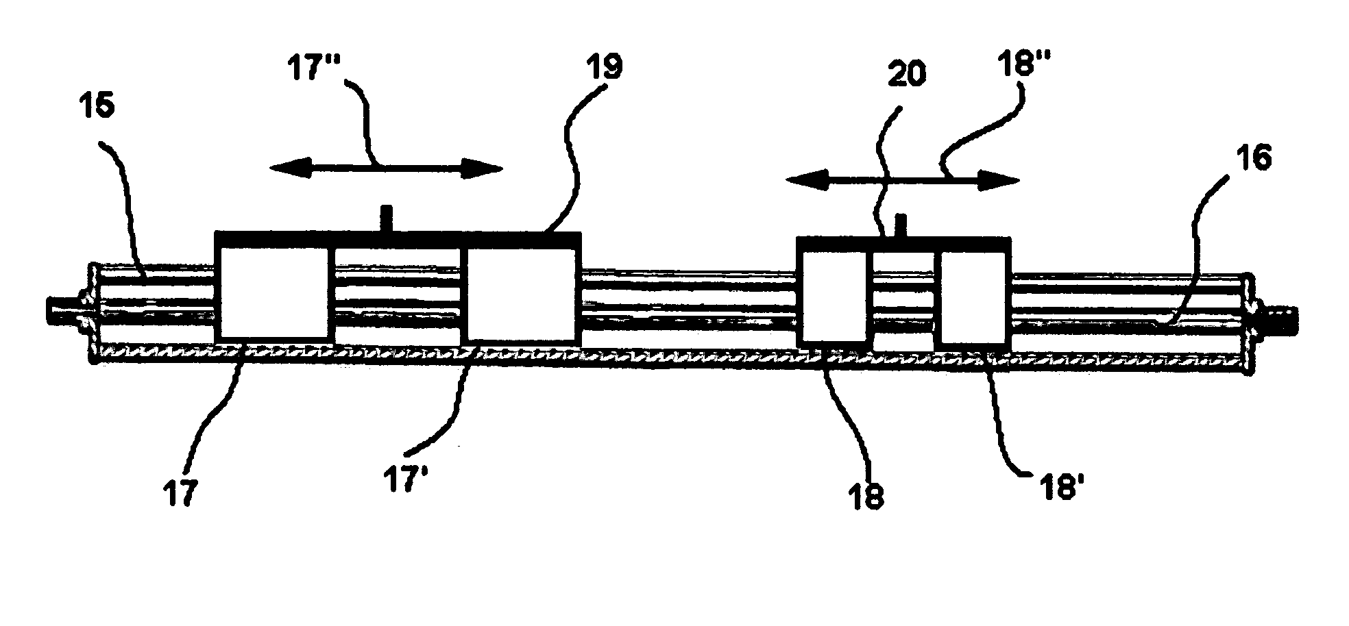
[0042] The harmonic reflective tuner, described by FIG. 8, consists of a housing (41), a slab-line ...


PUM


Abstract

The present invention discloses a harmonic reflective tuner system consisting of a radio-frequency (RF) or microwave transmission line having a longitudinal axis, containing two harmonic resonators sliding on the central conductor, where the harmonic resonators are comprising a pair of identical RF slugs, mechanically attached together. The two harmonic resonators will reflect two harmonic frequencies of a base frequency F0. The harmonic reflective tuner of this invention has an input and output, said input being connected to the DUT trough a diplexer in parallel with the fundamental tuner.

Description

CROSS REFERENCE TO RELATED APPLICATIONS [0001] U.S. Patent Documents 3851271November, 1974Cooke et al.331 / 474267532May, 1981Saleh333 / 334535307August, 1985Tsukii333 / 354751480June, 1988Kunz et al.333 / 1295079507January, 1992Ishida et al.324 / 6455363060November, 1994Kohno330 / 2865406224April, 1995Mikami et al.330 / 2776297649Oct. 2, 2001Tsironis324 / 6426674293Jan. 6, 2004Tsironis324 / 638OTHER REFERENCES [0002] LANGE Julius, Microwave Transistor Characterization Including S-Parameters, Texas Instruments, in Hewlett Packard Application Note 95 [0003] KESHISHIAN Richard, VSWR Tuner, MACOM Application Note AN0004 [0004] CUSACK Joseph M., PERLOW Stewart M., PERLMAN Barry S., Automatic Load Contour Mapping for Microwave Power Transistors; IEEE Transactions on Microwave Theory and Techniques, vol. MMT-22, No. 12, December 1974, pp 1146-1152. [0005] SECHI F., PAGLIONE R., PERLMAN B., BROWN J., A Computer-Controlled Microwave Tuner for Automated Load Pull, RCA Review, vol. 44 December 1983, pp 566-58...

Claims


Application Information

Patent Timeline
Patent Type & Authority Applications(United States)
IPC IPC(8): H01P1/00
CPCH01P1/212
Inventor BOULERNE, PHILIPPE
Owner BOULERNE PHILIPPE
Why Eureka
Try Eureka