

Liquid specimen analysis disk assembly
a technology of liquid specimens and disks, applied in the direction of material analysis, instruments, withdrawing sample devices, etc., can solve the problems of manual application of sealing sheets, reducing handling ease, and sealing sheets liable to be displaced from a due position
- Summary
- Abstract
- Description
- Claims
- Application Information
AI Technical Summary
Benefits of technology
Problems solved by technology
Method used
Image

Examples
embodiment 1
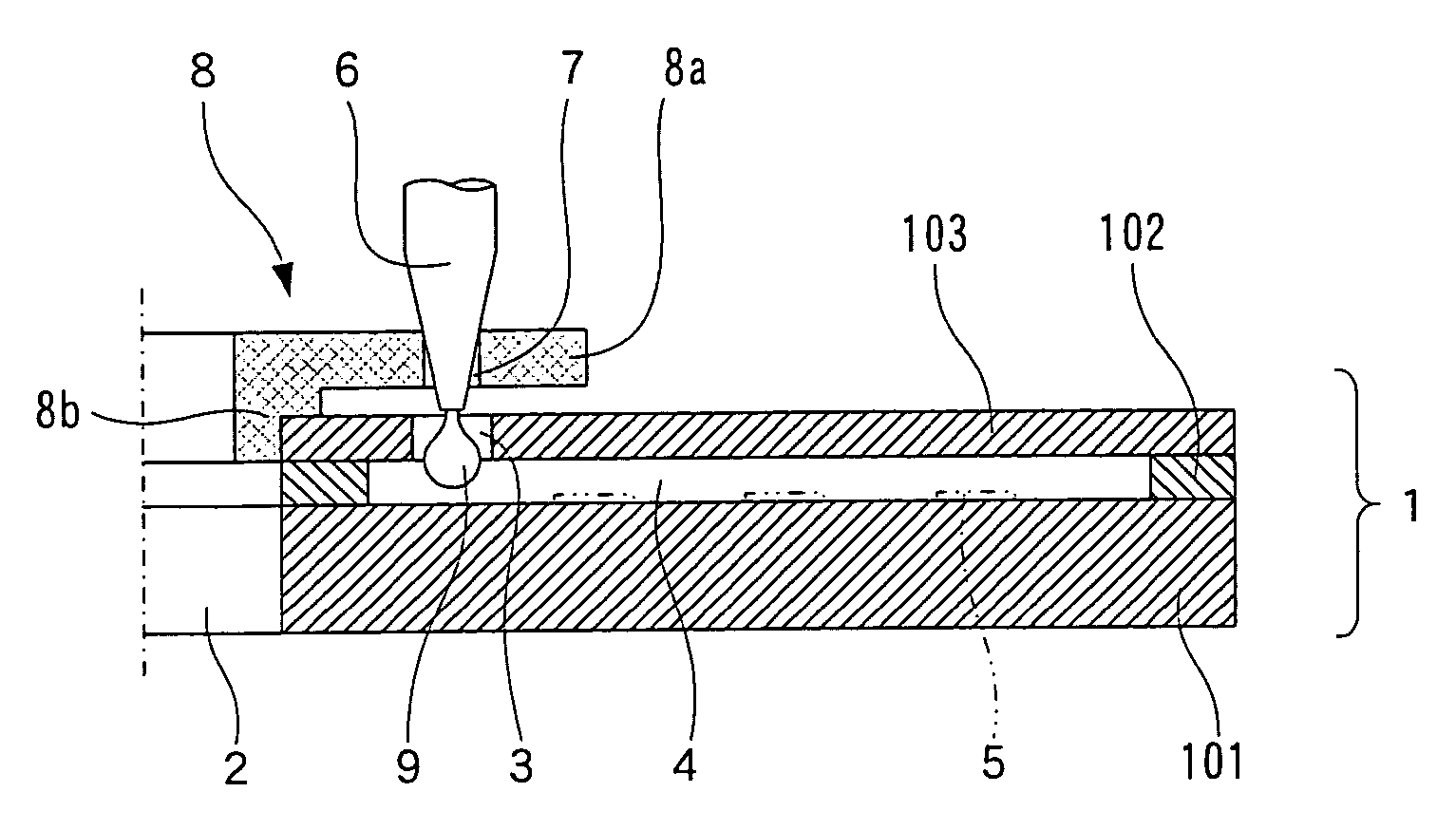
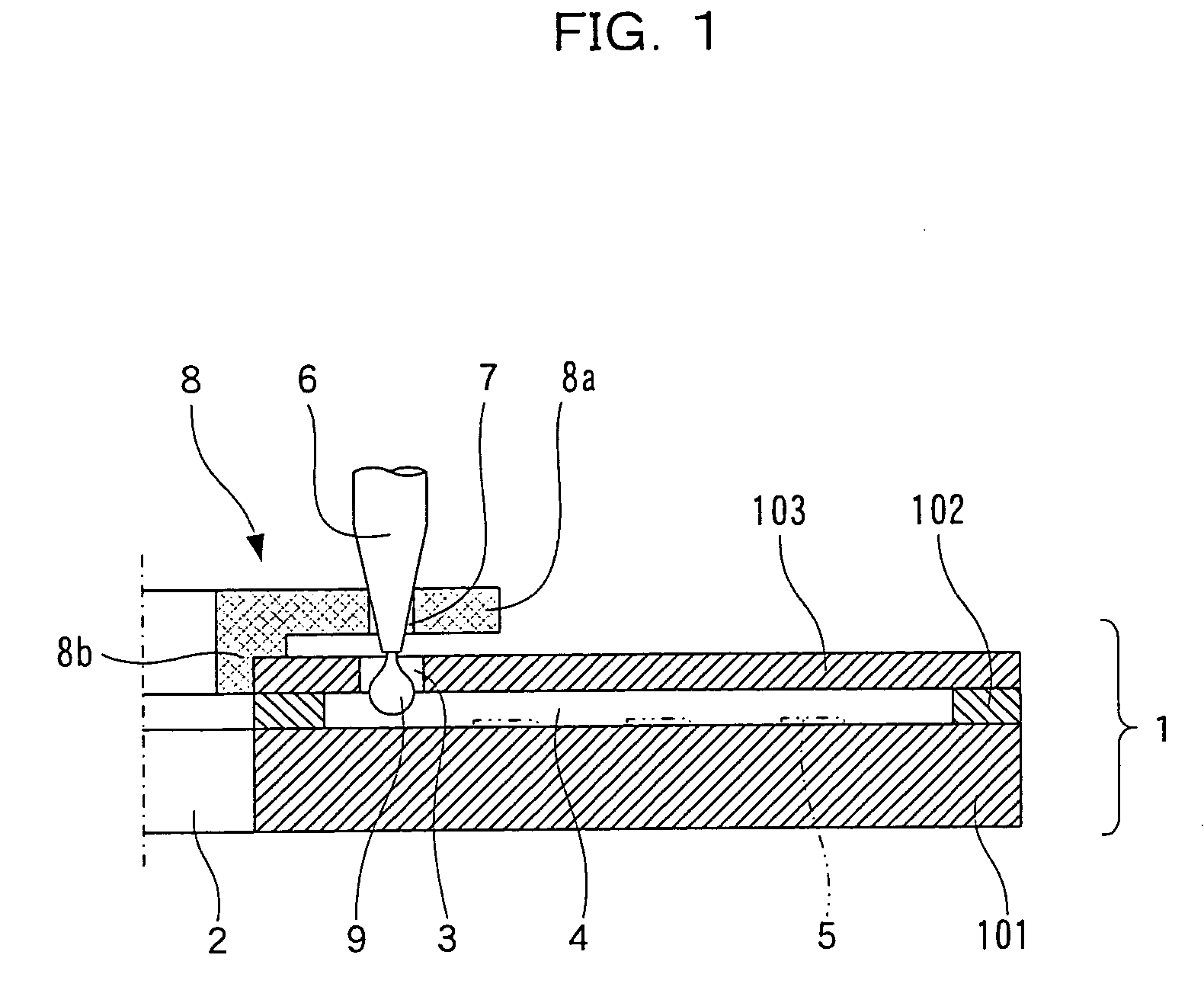
[0051]FIG. 1 is an enlarged vertical sectional view illustrating a part of a liquid specimen analysis disk assembly according to Embodiment 1 of the present invention, and FIG. 2 is an exploded perspective view of the liquid specimen analysis disk assembly. This liquid specimen analysis disk assembly is related to claim 1.
[0052] As shown in FIGS. 1 and 2, the liquid specimen analysis disk assembly includes a disk 1 having substantially the same construction as the conventional disk described with reference to FIG. 18. The disk 1 has a disk shape as a whole, and includes a plurality of specimen injection ports 3 provided in a front surface thereof around a center hole 2, and channels 4 provided therein in communication with the respective specimen injection ports 3 as extending radially from the respective specimen injection ports 3.
[0053] The disk 1 has a three-tier structure including a first plate (disk substrate) 101, a second plate (disk adhesion tier) 102 and a third plate (d...
embodiment 2
[0070]FIG. 4 is an enlarged vertical sectional view illustrating a part of a liquid specimen analysis disk assembly according to Embodiment 2 of the present invention. This liquid specimen analysis disk assembly is related to claims 2, 3 and 4.
[0071] The liquid specimen analysis disk assembly according to Embodiment 2 has substantially the same construction as the disk assembly according to Embodiment 1, but is different in the shape of each of the guide holes 7 of the guide member 8.
[0072] The guide holes 7 of the guide member 8 are each tapered so that a lower end opening thereof opposed to the specimen injection port 3 has a smaller diameter than an upper end opening thereof facing away from the specimen injection port 3. Further, the lower end opening of the guide hole 7 has an inner diameter slightly greater than the outer diameter of the distal end of the conical distal portion 6 of the specimen injector, and has a smaller inner diameter than the specimen injection port 3.
[...
embodiment 3
[0077]FIG. 5 is an enlarged vertical sectional view illustrating a part of a liquid specimen analysis disk assembly according to Embodiment 3 of the present invention. This liquid specimen analysis disk assembly is related to claims 5 and 6.
[0078] The liquid specimen analysis disk assembly according to Embodiment 3 has substantially the same construction as the disk assembly according to Embodiment 1, but differs in that the guide member 8 has tubular projections 8c provided on the lower surface of the flange 8a thereof as surrounding the respective guide holes 7. The tubular projections 8c each have a distal end having an outer diameter smaller than the inner diameter of the specimen injection port 3.
[0079] Therefore, even if the specimen 9 ejected from the distal portion 6 of the specimen injector adheres onto the interior surface of the guide hole 7, the specimen does not spread outward beyond the tubular projection 8c, so that the specimen adhesion area can be minimized. Even ...
PUM
 Abstract
Description
Claims
Application Information