
Magnetic recording apparatus

Active Publication Date: 2006-02-02
TDK CORPARATION
View PDF19 Cites 4 Cited by
  • Summary
  • Abstract
  • Description
  • Claims
  • Application Information

AI Technical Summary

Benefits of technology

[0011] In view of the foregoing circumstances, it is an object of the present invention to provide a magnetic recording apparatus which, while using a member mountable within a limited space in the apparatus, fully suppresses changes in output characteristics of a magnetic head without magnetically affecting the other members so much.
[0019] More preferably, the magnetic material further contains a permanent magnet. This makes it easier to set the strength of the magnetic field of the magnetic field applying part to an appropriate range.

Problems solved by technology

However, there have been cases where the conventional magnetic recording apparatus cause changes in output characteristics such as decreases in output and disorders in the symmetry of output waveforms in the magnetic head when used in a severe environment accompanying a large fluctuation in temperature.
Such changes in output characteristics are likely to result in read errors and the like from magnetic recording media, whereby stable operations are harder to attain.
However, for employing this method in an actual magnetic recording apparatus, it has been found necessary to mount a member for applying the magnetic field within a limited space in the apparatus, whereas the magnetic field generated by this member may magnetically affect magnetic recording media or the like, and so forth, which are problems to be solved in order to achieve practical uses.

Method used


Image

  • Magnetic recording apparatus
  • Magnetic recording apparatus
  • Magnetic recording apparatus

Examples


example 1

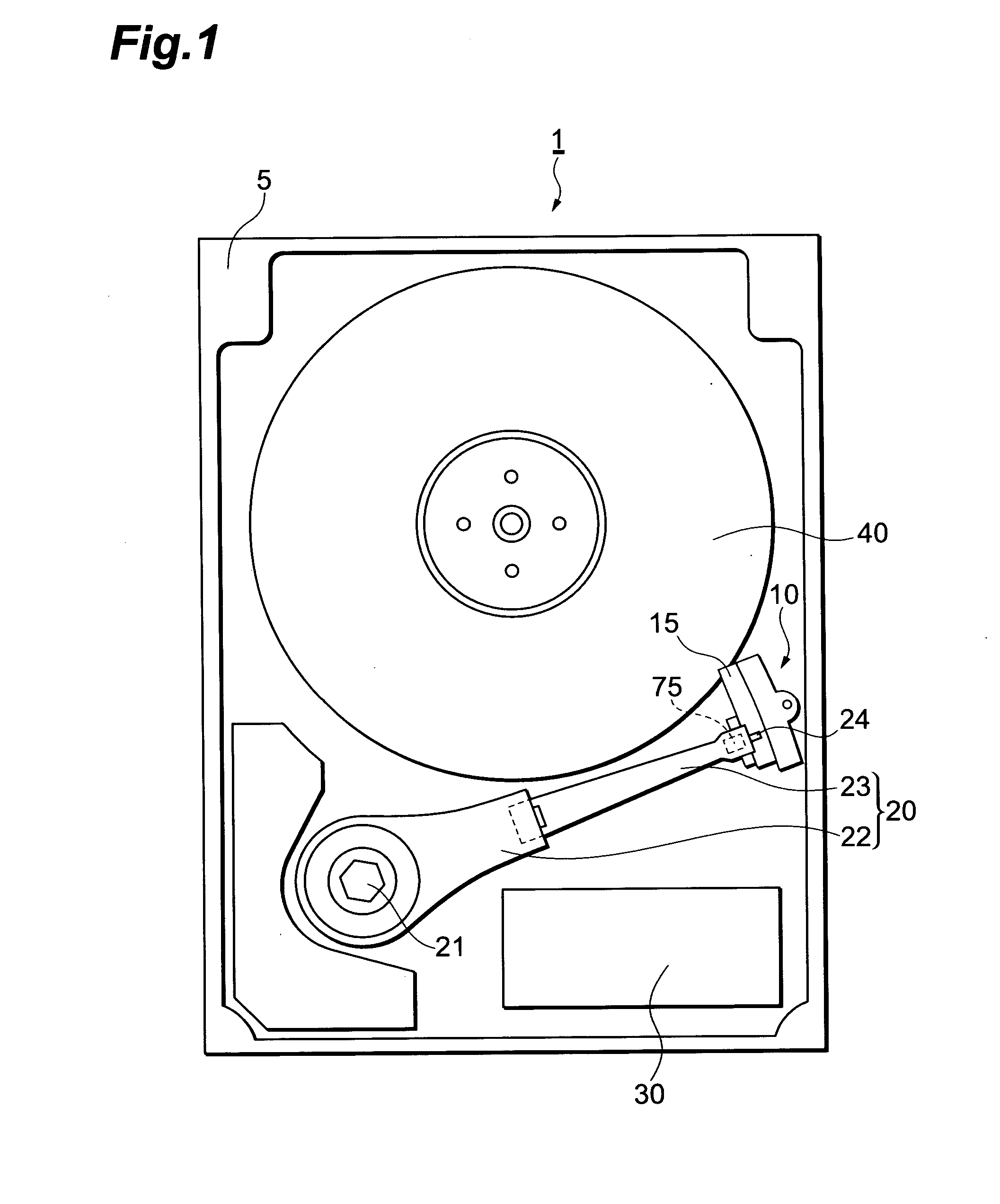
[0055] A magnetic head including a magnetoresistive device was left for 15 hours in an environment at 125° C., so as to apply a temperature stress thereto. A magnetic field in a direction (the direction indicated by D in FIG. 4) perpendicular to the main surface of the head slider 75 was applied to the magnetic head subjected to the temperature stress while changing the strength and polarity from −100 Oe to 100 Oe (first step), and again while changing the strength and polarity from 100 Oe to −100 Oe (second step). At that time, the relationship between the voltage as an output signal of the magnetoresistive device and the strength of the external magnetic field (the relationship between voltage and external magnetic field) was measured. Thereafter, the magnetic head was placed at a position within the groove of the magnetic field applying part made as mentioned above, and a magnetic field having a strength of about 800 Oe was applied thereto, so as to remagnetize the magnetic head....

example 2

[0057] Using a magnetic head prepared separately from that of Example 1, the same experiment as that of Example 1 was carried out. FIG. 9 shows the results. In this case, the magnitude of voltage decreased from its initial state in a region where the polarity of magnetic field was negative (on the left side of the graph) as shown in the graph of (b) in FIG. 9, whereby the symmetry of output waveforms deteriorated as a whole. However, the magnetic head having the magnetic field applied thereto was seen to restore an output characteristic similar to that of the initial state (the graph of (a)) as shown in the graph of (c).

[0058] The present invention provides a magnetic recording apparatus which, while using a member mountable within a limited space in the apparatus, fully suppresses changes in output characteristics of a magnetic head without magnetically affecting the other members so much.


PUM


Abstract

A magnetic recording apparatus comprises a magnetic disk; a magnetic head, including a magnetoresistive device, for reading information from the magnetic disk; an arm attached to the magnetic head and swings so as to load and unload the magnetic head to or from the magnetic disk; a magnetic field applying part disposed close to the magnetic disk, made of a magnetic material, and formed with a groove for surrounding the magnetic head; and a holding part for holding the arm such that the unloaded magnetic head stays at a position surrounded by the groove; whereas the magnetic material contains a plastic magnet.

Description

BACKGROUND OF THE INVENTION [0001] 1. Field of the Invention [0002] The present invention relates to a magnetic recording apparatus such as a magnetic disk drive. [0003] 2. Related Background of the Invention [0004] As magnetic recording apparatus, those employing magnetic recording media such as magnetic disks with magnetic heads using magnetoresistive devices have widely been in use. It is necessary for these magnetic recording apparatus to have an excellent resistance against external shocks, prevent malfunctions such as read errors from occurring, and so forth. [0005] Therefore, a magnetic recording apparatus equipped with a so-called load / unload mechanism which holds a magnetic head in a state unloaded from a magnetic recording medium when not operated and loads the magnetic head again at the time of operation in order to improve the shock resistance of the magnetic recording apparatus has been known (see, for example, Japanese Patent Application Laid Open No. HEI 11-345471). [...

Claims


Application Information

Patent Timeline
IPC IPC(8): G11B5/33
CPCG11B5/39G11B21/22G11B5/54G11B5/40
Inventor ANTOKU, YOSUKE
Owner TDK CORPARATION
Learn More