Wireless network management with antenna control

a wireless network and control technology, applied in the field of wireless communications, can solve the problems of difficult to isolate variables in practice, complicate path loss calculation, and difficult to determine suitable coverage areas for a set of access points in a wireless local area network

Inactive Publication Date: 2006-02-02
CISCO TECH INC
View PDF8 Cites 29 Cited by
  • Summary
  • Abstract
  • Description
  • Claims
  • Application Information

AI Technical Summary

Benefits of technology

[0019] As will be realized, the invention is capable of other and different embodiments and its several details are capable of modifications in various respects, all without departing from the invention. Accordingly, the drawing and description are to be regarded as illustrative and not restrictive.

Problems solved by technology

However, it can be difficult in practice to isolate these variables and thereby properly establish coverage areas 22.
Consequently, there may be a power loss associated with the cable length that complicates the path loss calculation.
These factors can also vary across different wireless channels and / or bands, thereby making it difficult to determine suitable coverage areas for a set of access points in a wireless local area network.
Either a bad assumption or incorrect knowledge of the antenna gain and / or type will cause invalid results by the network management entity 18 regarding network coverage.
This uncertainty in antenna gain contributes to the problems of locating clients within a wireless local area network.
But if the actual antenna gain is different than that assumed, the values used in the calculations will be different than the actual values, and, thus, the path loss calculation will not be correct, resulting in faulty distance determinations.
This results in uncertainty in locating clients, since a client's location can only be estimated within an area of potential locations.
Also, since variance in signal strength may be the result of other environmental factors, such as internal reflections from metallic construction elements in the building, this contributes further to the uncertainty.
Additionally, current wireless local area network capabilities create problems from a regulatory standpoint.
However, this requirement is easily circumvented since it possible to obtain “off the shelf” external antennas that have higher antenna gains than can permissibly be used with a particular access point.
However, after-market adapters are now available that allow non-compliant antennas to be used.

Method used


Image

  • Wireless network management with antenna control
  • Wireless network management with antenna control
  • Wireless network management with antenna control

Examples


Embodiment Construction

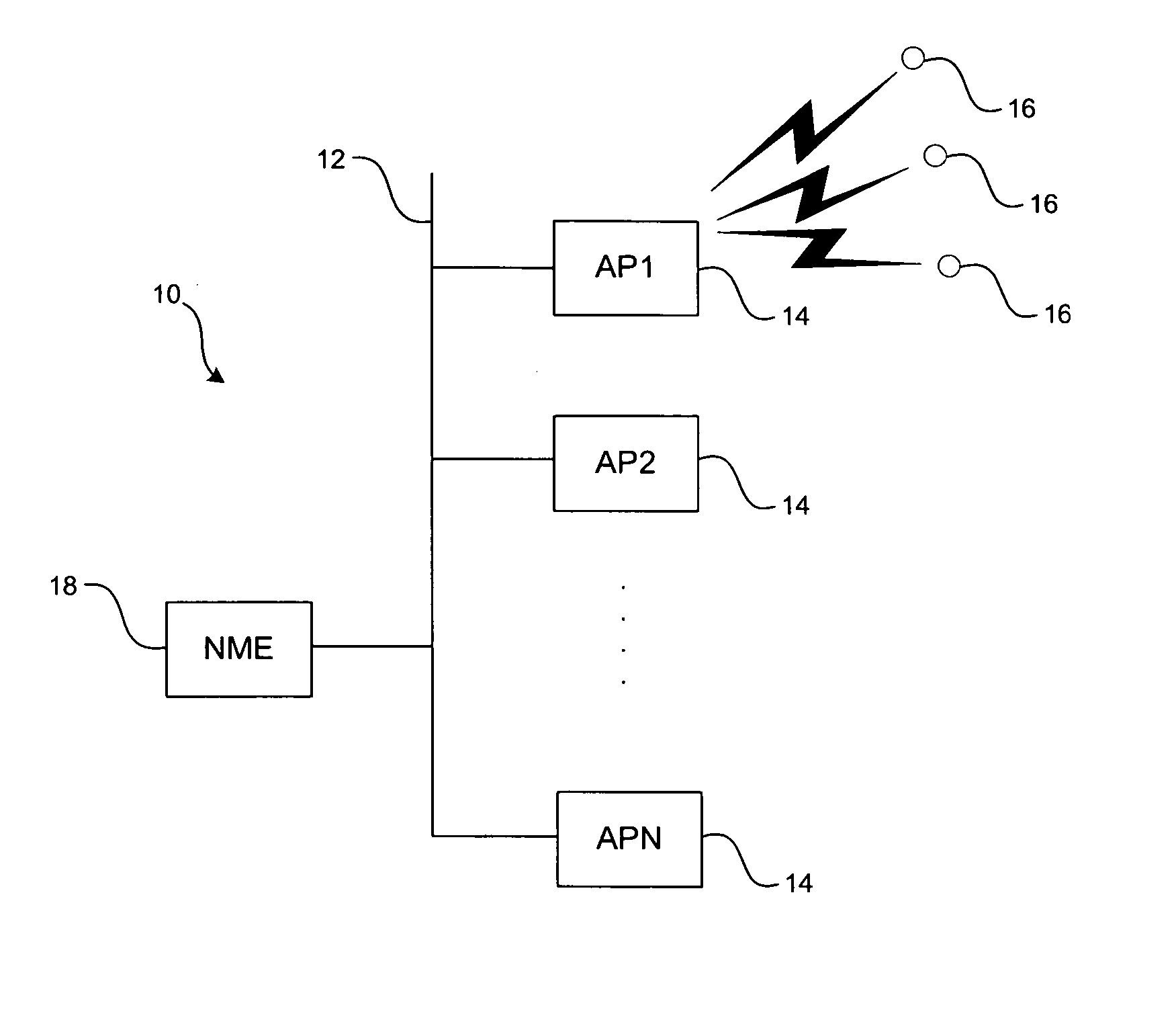
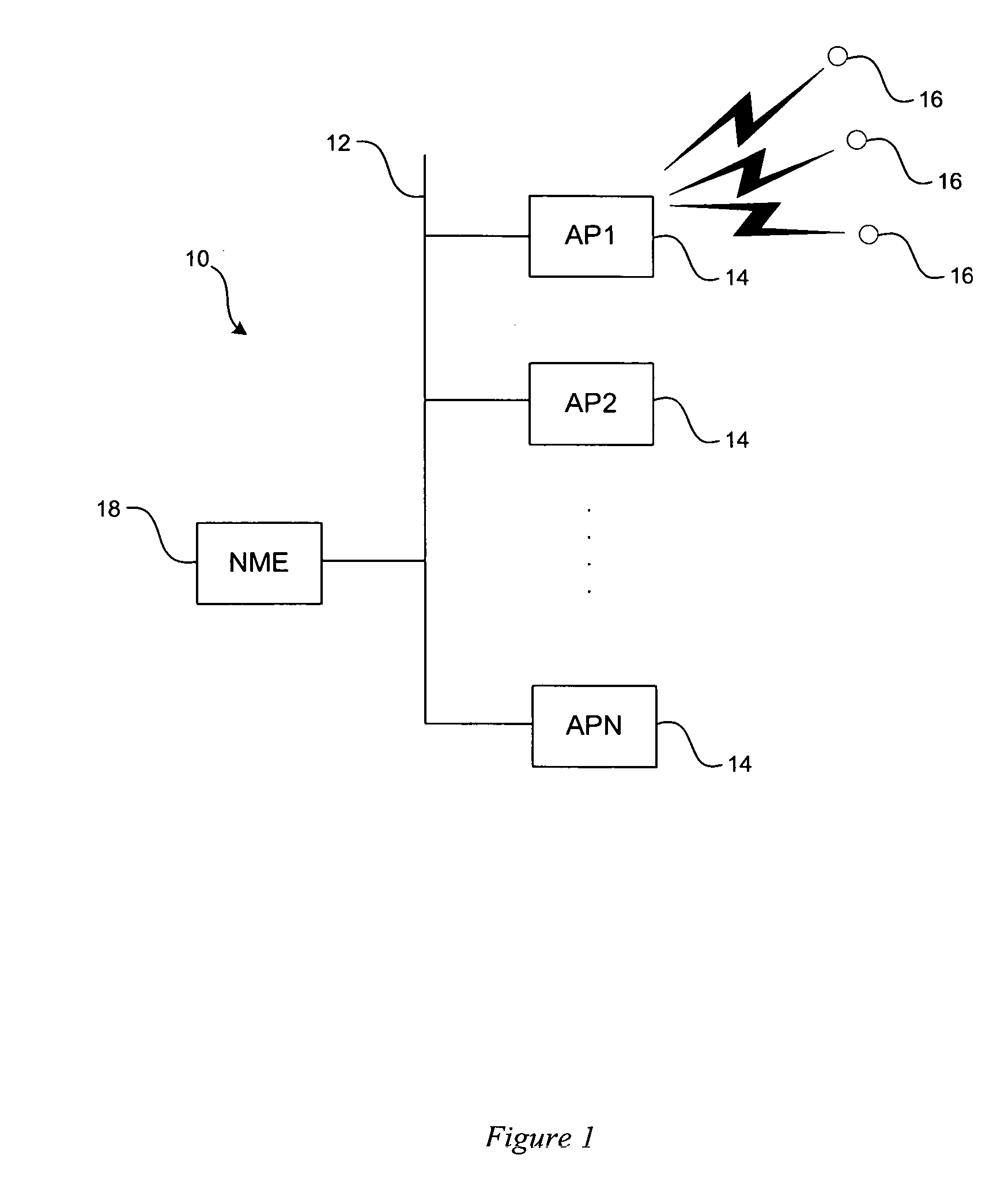
[0025] The present managed wireless local area network includes a network backbone that connects a number of wireless access points, for exchanging wireless telecommunications signals with wireless clients in the radio frequency (RF) band of the electromagnetic spectrum. The wireless access points each include an antenna assembly for transmitting and receiving signals at radio frequencies. In the preferred embodiment, the present system would communicate over one or both of the 2.4 and 5 Gigahertz (GHz) wireless bands, in accordance with the Institute of Electrical and Electronics Engineers (IEEE) 802.11 protocols. Of course, it should be appreciated that the present embodiments could be used with any wireless communication device, operating under any wireless band, including large communications stations and small, hand-held units, all without departing from the scope of the invention.

[0026] As shown in FIG. 3, the present system includes a managed wireless local area network 50 i...


PUM


Abstract

A method and apparatus for managing a wireless local area network are disclosed. The network includes one or more wireless access points, each including a radio frequency assembly having a variable power output, and an antenna assembly for transmitting and receiving wireless signals. A microcontroller is included for sending a transmission characteristics signal to the wireless local area network. A network manager is included for receiving the transmission characteristics signal and selectively controlling the variable power output of the radio frequency assembly to a predetermined power level.

Description

BACKGROUND OF THE INVENTION [0001] The present system is generally directed to the field of wireless communications. The present system has particular applicability in a wireless access point (AP) or wireless bridge (BR) of the type used in a wireless local area network (WLAN) and employing an antenna system for exchanging wireless signals. [0002] As shown in FIG. 1, a managed wireless local area network (WLAN) 10 includes a network backbone 12, preferably an Ethernet network, and at least one wireless access point (AP) 14 (e.g., AP1, AP2 . . . APN, as indicated). Each access point 14 wirelessly communicates over radio frequencies with a plurality of wireless clients 16. The operation and performance of the wireless local area network 10 is typically handled by a network manager or network management entity (NME) 18. A network manager or network management entity 18 is used to calculate and determine a suitable coverage area that an access point can provide as will be shown and desc...

Claims


Application Information

Patent Timeline
Patent Type & Authority Applications(United States)
IPC IPC(8): H04B7/00
CPCG01R29/0878H04B17/102H01Q7/00
Inventor AMOS, JAMES A.
Owner CISCO TECH INC
Why Eureka
Try Eureka