Coupling unit for coupling an optical transmitting and/or receiving module to an optical fiber connector

Inactive Publication Date: 2006-02-02
II VI DELAWARE INC
View PDF8 Cites 4 Cited by
  • Summary
  • Abstract
  • Description
  • Claims
  • Application Information

AI Technical Summary

Benefits of technology

[0021] A convex formation of the end face toward the optical fiber makes improved securement of physical contact possible with respect to the end face of an optical fiber. An alignment of the other end face obliquely in relation to the longitudinal axis of the glass component has the effect of minimizing reflections back into the fiber.
[0022] The glass component preferably has a refractive index tha

Problems solved by technology

However, such a coupling unit is relatively expensive to produce and requires a relatively high level of assembly effort.
A large number of high-precision, relatively expensive individual parts

Method used


Image

  • Coupling unit for coupling an optical transmitting and/or receiving module to an optical fiber connector
  • Coupling unit for coupling an optical transmitting and/or receiving module to an optical fiber connector

Examples


Embodiment Construction

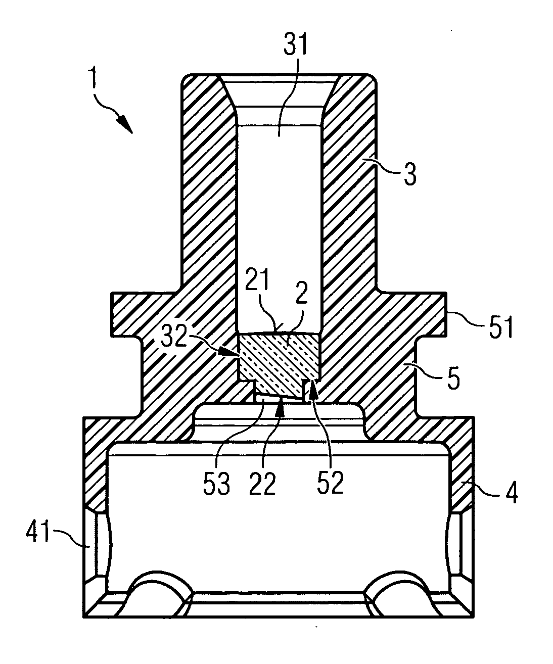
[0028]FIG. 1 shows a coupling unit 1 with a receiving region 3, a connecting region 4 and a cylindrical glass component 2. The coupling unit 1 is formed as a one-piece injection molding—apart from the glass component 2.

[0029] The receiving region 3 is formed as an elongate sleeve, which provides a precision bore 31 for a connector ferrule with a central single-mode glass fiber (not represented) to be introduced into the elongate sleeve 3. The end face of such a glass fiber is in this case polished together with the end face of the connector ferrule such that it is convex perpendicularly in relation to the radiating direction or longitudinal axis of the glass fiber.

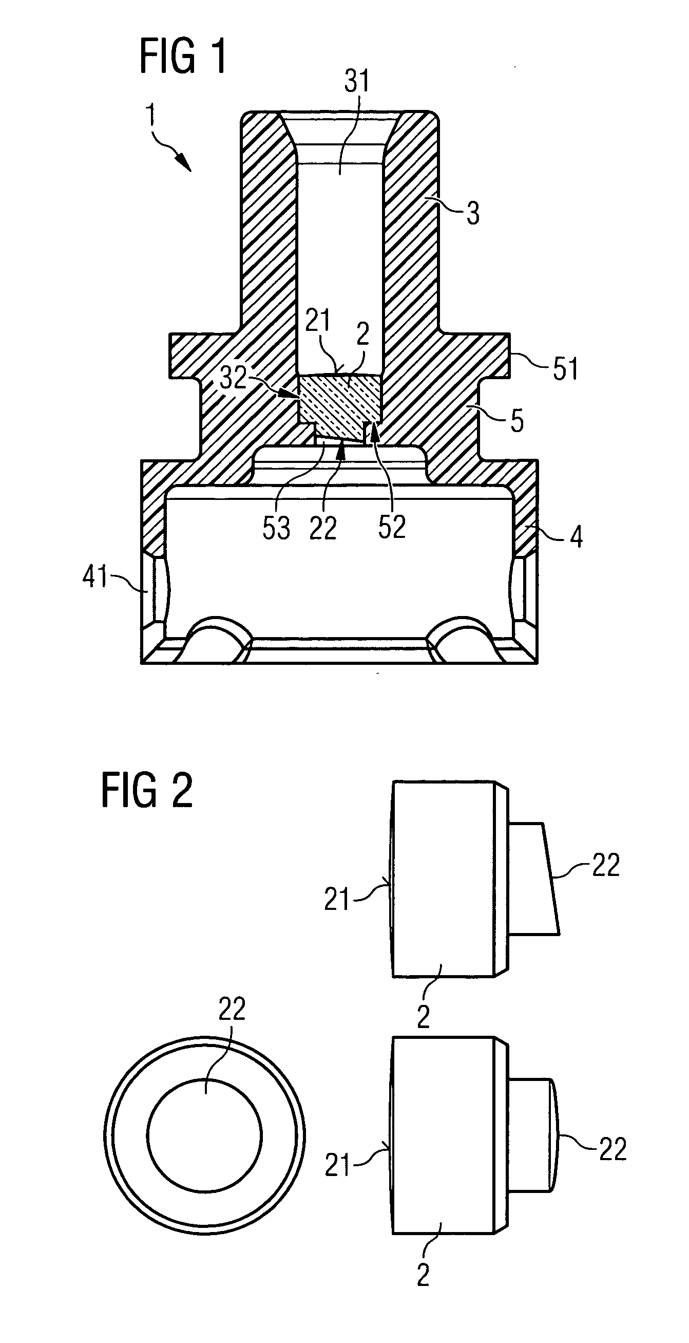
[0030] The precision bore 31 is axially adjoined by a further bore 32, in which the glass component 2 is arranged. The bore 32 for receiving the glass component 2 has in this case a slightly smaller diameter in comparison with the precision bore 31. For example, the diameter of the bore 32, which receives the glass compo...


PUM


Abstract

A coupling unit for coupling an optical transmitting and/or receiving module to an optical fiber connector. The coupling unit has a connecting region, which can be connected to a transmitting and/or receiving module, a receiving region, which receives an optical fiber connector, and a glass component, via which light is coupled directly between an optical fiber inserted into the receiving region and a coupled-on transmitting and/or receiving module. In this case, the coupling unit is formed as a plastic part apart from the glass component. The glass component is introduced into a bore in the plastic part.

Description

RELATED APPLICATION [0001] The present application is claims priority of U.S. Patent Application Ser. No. 60 / 592,437 filed by Frank Meyer-Guldner on Jul. 30, 2004.FIELD OF THE INVENTION [0002] The invention relates to a coupling unit for coupling an optical transmitting and / or receiving module to an optical fiber connector. The coupling unit according to the invention is used in particular for coupling a laser diode or receiving diode arranged in a TO (Transistor Outline) package to a single-mode glass fiber. BACKGROUND OF THE INVENTION [0003] It is known to couple an optical fiber arranged in an optical connector to a transmitting and / or receiving module by means of a coupling unit. Light emerging from the optical fiber is thereby directed onto the photosensitive surface of a receiving element, in particular a photodiode, and / or light emitted by a transmitting element, in particular a laser diode, is coupled into the optical fiber. [0004] In order to minimize reflections at the lig...

Claims


Application Information

Patent Timeline
IPC IPC(8): G02B6/36
CPCG02B6/4207G02B6/4204
Inventor MEYER-GULDNER, FRANK
Owner II VI DELAWARE INC
Why Eureka
Try Eureka