
Composite, ordered material having sharp surface features

Active Publication Date: 2006-02-02
UT BATTELLE LLC
View PDF5 Cites 40 Cited by
  • Summary
  • Abstract
  • Description
  • Claims
  • Application Information

AI Technical Summary

Benefits of technology

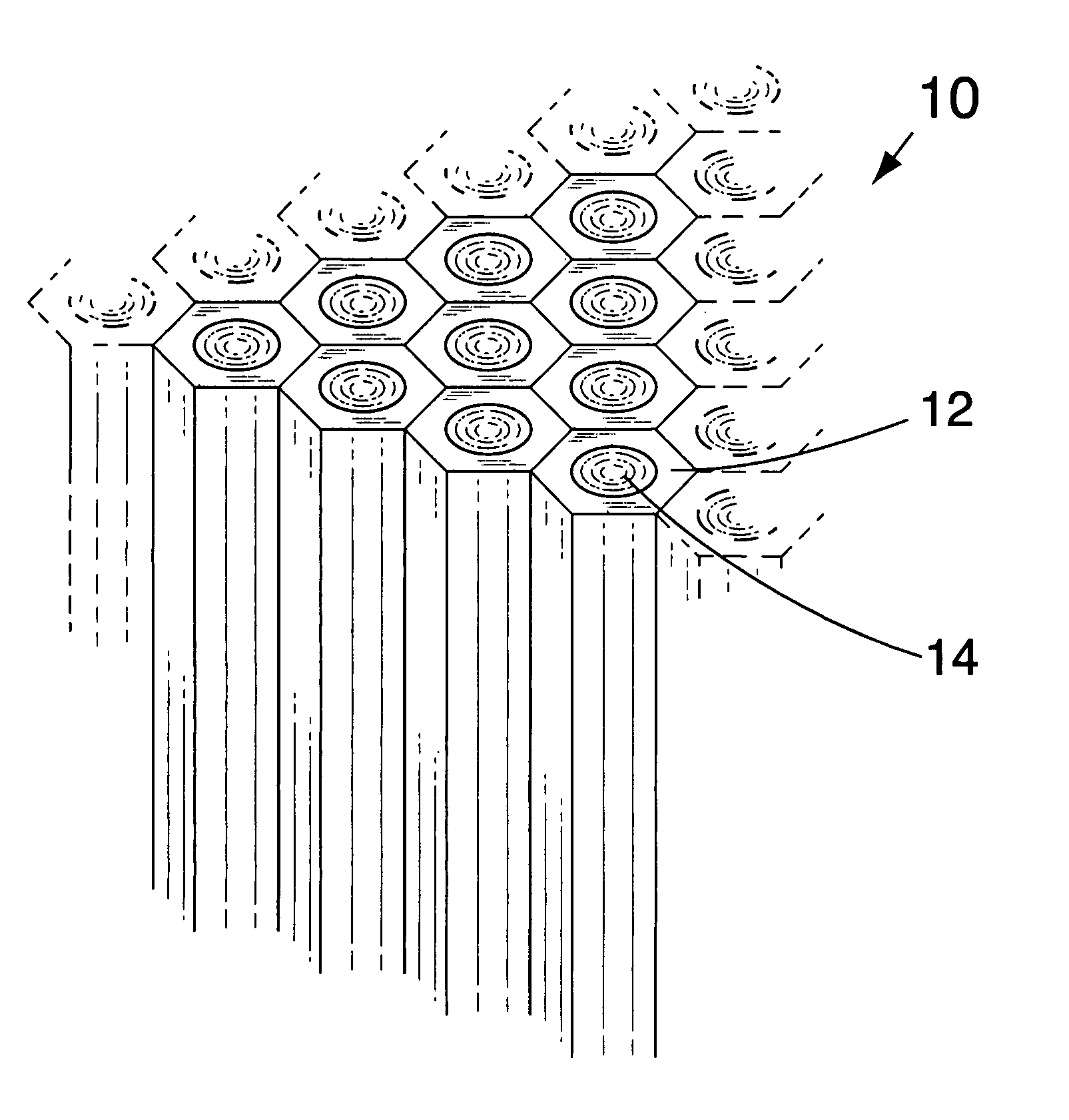
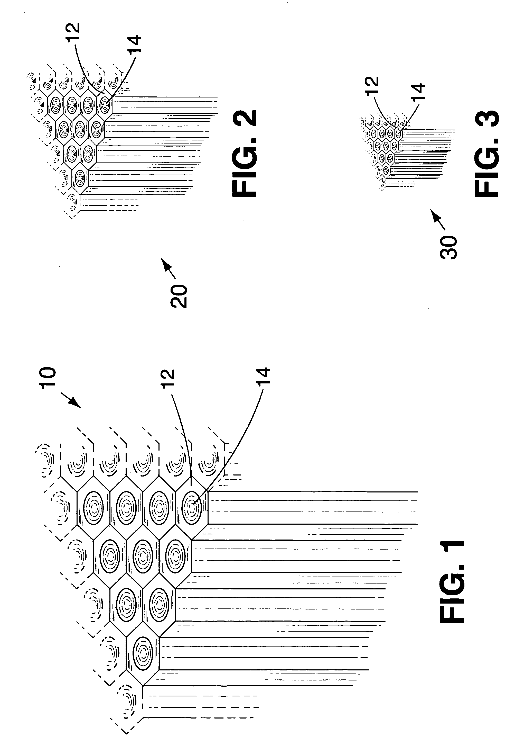
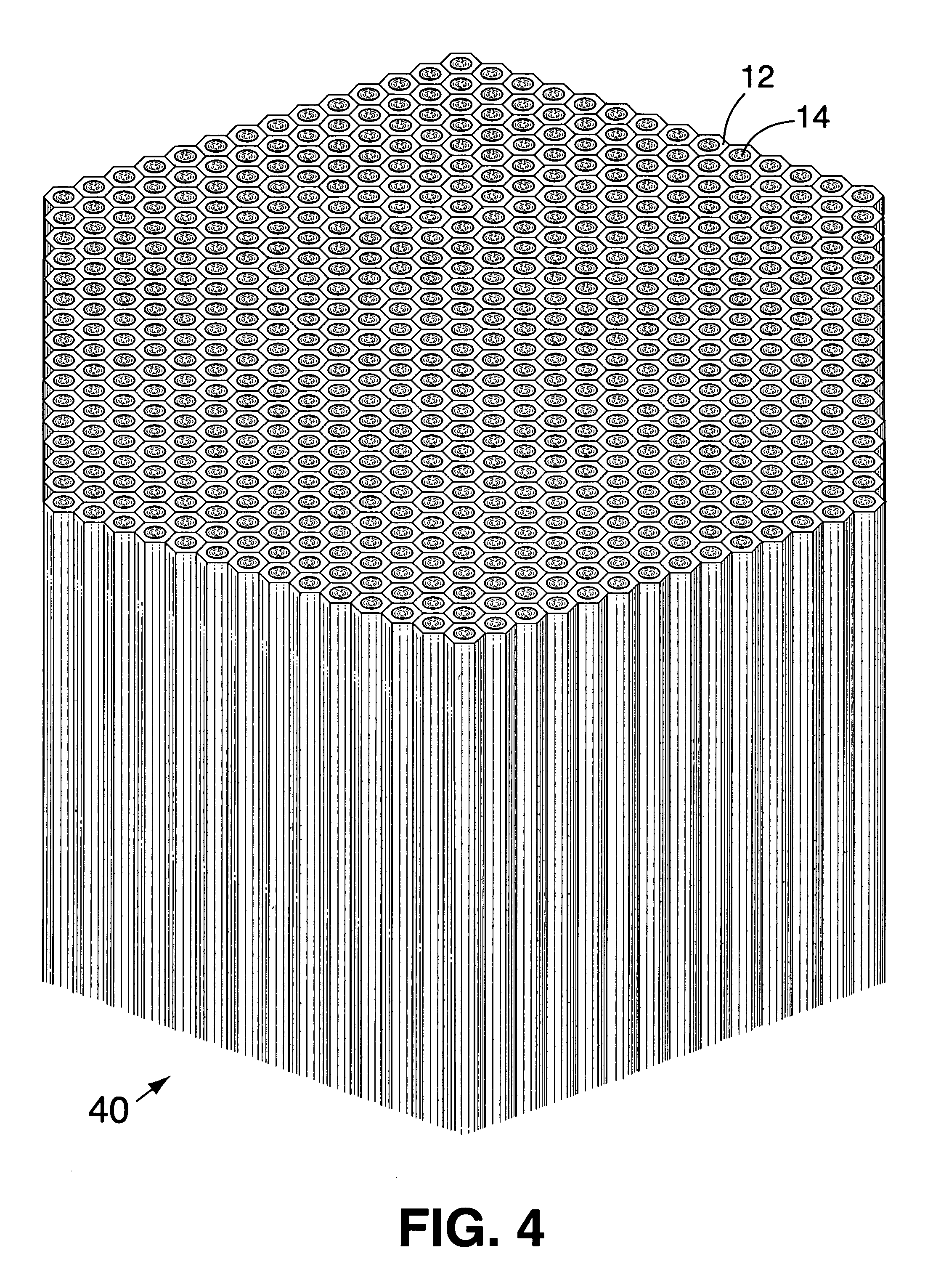
[0009] In accordance with one aspect of the present invention, the foregoing and other objects are achieved by a composite material having sharp surface features including a recessive phase and a protrusive phase, the recessive phase having a higher susceptibility to a preselected etchant than the protrusive phase, the composite material having an etched surface wherein the protrusive phase protrudes from the surface to form a sharp surface feature.
[0010] In accordance with another aspect of the present invention, a spiked article including a composite material having sharp surface features including a recessive phase and a protrusive phase, the recessive phase having a higher susceptibil

Problems solved by technology

Even in the process for producing microchannel or nanochannel glass, the materials and etchant are chosen to result in steep sidewalls and extremely high aspect ratios.

Method used


Image

  • Composite, ordered material having sharp surface features
  • Composite, ordered material having sharp surface features
  • Composite, ordered material having sharp surface features

Examples


example i

[0052] In accordance with the present invention, glass rods having a Sylvania SG12™(equivalent to Corning 0120™) core glass as the less etchable protrusive phase and Corning 8161™ cladding (matrix glass) as the more etchable recessive phase were bundled, heated to a temperature sufficient to soften the rods, and drawn to reduce the diameter thereof. The resulting rod was cut into sections that were re-bundled and redrawn. The above process was repeated until the diameter of the core glass was reduced to 5 μm and spaced apart about 7 μm. The rod was cut into sections, bundled, and fused to form a shorter, thicker rod having a diameter of about 1.5 cm. A thin plate was cut transversely from the end of the rod, polished, and subject to etching with HF at room temperature for a period of 20 min. to produce a spiked surface on the disk. The spikes were about 12 μm tall.

[0053]FIG. 6 is an oblique photomicrograph of a spiked glass plate made in accordance with Example I. The recessive are...

example ii

[0057] A spiked disk made in accordance with Example I was immersed in a solution of (tridecafluoro-1,1,2,2 tetrahydrooctyl) trichlorosilane in hexanes to form a self-assembled hydrophobic monolayer on the spiked surface. The resulting disk exhibited super-hydrophobic properties.

[0058] A super-hydrophobic disk made in accordance with Example II was tested for super-hydrophobic properties. FIG. 10 shows a drop of water eluted from a syringe directly onto the disk. The drop has an apparent contact angle greater than 175°, and approaching 180°. FIG. 11 shows a drop of water eluted from a syringe directly onto a flat, hydrophobic-coated glass surface for comparison with the present invention. The drop has an apparent contact angle of about 105°.

[0059]FIGS. 12-14 are frames excerpted from a motion picture sequence showing a drop of water eluted from a syringe falling toward the super-hydrophobic disk (FIG. 12), falling onto and compressing against the super-hydrophobic disk (FIG. 13), ...


PUM

PropertyMeasurementUnit
Hydrophobicityaaaaaaaaaa
Glass structureaaaaaaaaaa

Abstract

A composite material having sharp surface features includes a recessive phase and a protrusive phase, the recessive phase having a higher susceptibility to a preselected etchant than the protrusive phase, the composite material having an etched surface wherein the protrusive phase protrudes from the surface to form a sharp surface feature. The sharp surface features can be coated to make the surface super-hydrophobic.

Description

[0001] The United States Government has rights in this invention pursuant to contract no. DE-AC05-00OR22725 between the United States Department of Energy and UT-Battelle, LLC.CROSS-REFERENCE TO RELATED APPLICATION [0002] This patent application is related to another patent application by D'Urso and Simpson entitled “Composite, Nanostructured, Super-Hydrophobic Material” and filed on even date herewith, the entire disclosure of which is incorporated herein by reference. FIELD OF THE INVENTION [0003] The present invention relates to composite materials, and more particularly to differentially etched, ordered materials having sharp surface features. The invention further relates to super-hydrophobic surfaces, and more particularly to differentially etched, ordered, sharp-featured, super-hydrophobic surfaces. BACKGROUND OF THE INVENTION [0004] Hydrophobic surfaces bind very weakly with water, which makes drops of water “bead up” on the surface. A hydrophobic surface is generally define...

Claims


Application Information

Patent Timeline
IPC IPC(8): B32B3/00C23F1/00
CPCB01L3/0244B01L3/0255B01L2200/12B01L2300/0819B05D5/083B82Y30/00Y10T428/24149C03C15/00C03C2204/08G01N33/54393H01J1/3044H01J9/025Y10T428/24479C03C4/00Y10T428/3154Y10T428/31678C03C11/00C03C17/28B82Y40/00
Inventor D'URSO, BRIAN R.SIMPSON, JOHN T.
Owner UT BATTELLE LLC
Learn More