
Dumbell adjustable in weight

Inactive Publication Date: 2006-02-02
CHERMACK DARREN PATRICK
View PDF24 Cites 64 Cited by
  • Summary
  • Abstract
  • Description
  • Claims
  • Application Information

AI Technical Summary

Benefits of technology

[0013] The primary objective of the present invention is to provide a compact and easy to use weight lifting system that is not hindered by clumsy design or functional limitations.

Problems solved by technology

Fixed dumbbells present a problem for storage in limited space, being that usually two of each weight increment takes up a significant amount of room.
Each set must also be purchased separately, making an entire set rather expensive.
A set of fixed dumbbells is also not very portable, specifically moving the entire set is very inconvenient.
Each of the existing designs has significant drawbacks.
They stricken with one or more of the following problems: they take too much time to change weight, are not useable by someone with large hands, are unwieldy, are difficult to change weights, or pose a safety hazard.
If the collars are loose or loosen during use, they pose a safety hazard because the weights can fall off the handle.
Although these designs show some promise, each has drawbacks and limitations.
These limitations include such elements as: external selection mechanisms which pose a safety hazard, mechanisms that are limited in their function, mechanisms that are overly complicated, mechanisms that prohibit general usefulness or user comfort, devices that would not be reliable or sturdy, or some combination of the above.
Some concepts that the present devices uses are mentioned in previously submitted material, but are not put together to make a safe, versatile, durable and user-friendly mechanism.
The rack-and-pinion system is not a new technology.

Method used


Image

  • Dumbell adjustable in weight
  • Dumbell adjustable in weight
  • Dumbell adjustable in weight

Examples


Embodiment Construction

[0028] Component List:

[0029]1. Handle Unit

[0030]2. Selection Knob

[0031]3. Extending Rods [0032]3a. Teeth

[0033]4. Endpiece

[0034]5. Grip

[0035]6. Drive Gear

[0036]7. Center Gear

[0037]8. Drive Axle

[0038]9. Spring Plunger [0039]9a. Ball [0040]9b. Spring

[0041]10. Indicator Window

[0042]11. Indicator Dial

[0043]12. Dial Drive Gear

[0044]13. Dial Reduction Gear

[0045]14. Dial Indicator Gear

[0046]15. Weight Unit

[0047]16. Weight Plate

[0048]17. Bar

[0049]18. Channel

[0050]19. Holes

[0051]20. Weights

[0052]21. Dimples

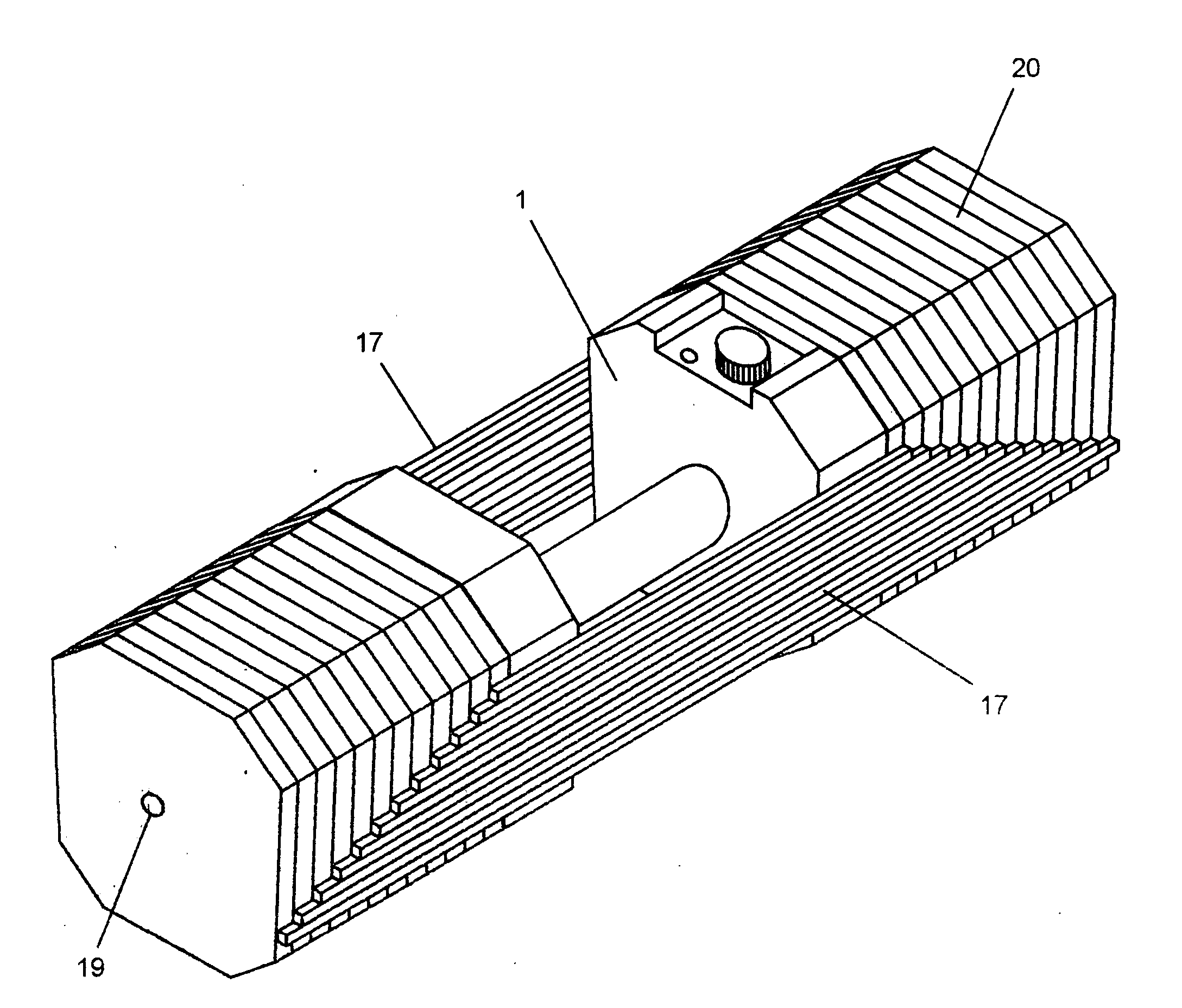
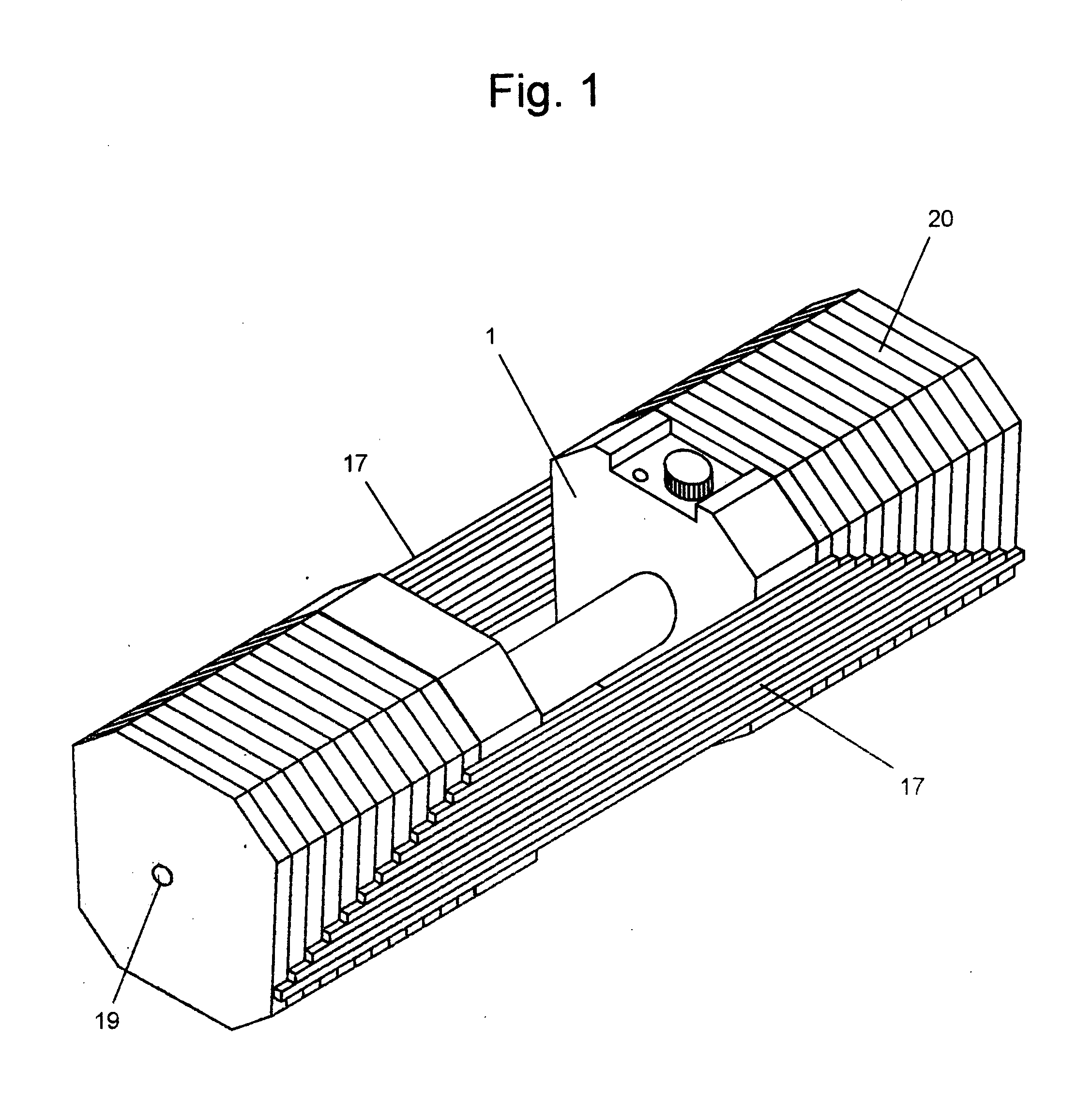
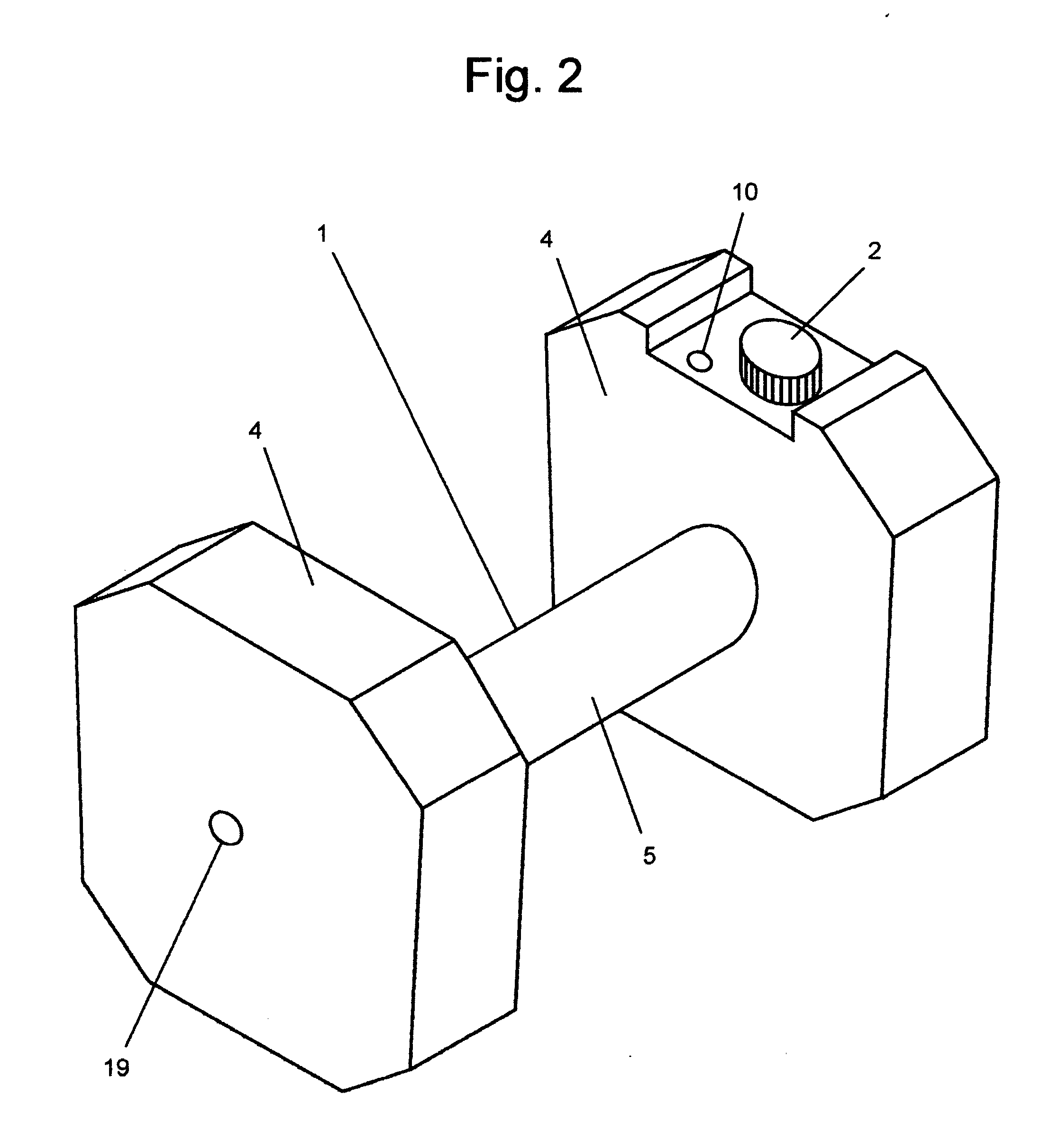
[0053] As shown in FIGS. 1-2, a dumbbell system of the present invention is shown, which comprises of (i) a handle unit 1, and (ii) a plurality of weights 20. The handle unit 1 consists of a grip 5 containing an internal mechanism for extending and retracting two extending rods 3, a selection device 2, two endpieces 4, and an indicator window 10 to display the currently selected weight.

[0054]FIGS. 3-4 show the mechanism within the grip. The selection knob 2 turns the ...


PUM


Abstract

An adjustable dumbbell featuring a handle containing an internal selection mechanism within series of nested weight units. The selection device is operated by a single action, in this case by turning a knob, which extends or retracts bars contained in the handle to attach a desired number of weight units to the handle.

Description

REFERENCES [0001] U.S. Patent Documents 6,186,928Mar. 19, 1999Chen6,196,952Mar. 8, 1999Chen6,500,101Aug. 11, 2000Chen6,228,003Mar. 17, 1998Hald et. al.6,261,022Feb. 9, 1999Dalebout et. al.5,637,064Oct. 13, 1995Olsen et. al.5,769,762Jun. 3, 1996Towley et. al.5,779,604Mar. 4, 1996Towley et. al.6,083,144May 4, 1999Towley et. al.5,971,899Jun. 19, 1998Towley et. al.6,033,350Sep. 29, 1997Krull5,839,997Jan. 22, 1998Roth et. al.FIELD OF INVENTION [0002] This invention relates to the exercise equipment field. It is focused toward free weights, utilizing weight-based resistance for exercise movements. BACKGROUND OF THE INVENTION [0003] Traditional dumbbells and barbells have been used for over a century for building body strength and continue to be used for general fitness, strength and endurance training, and physical rehabilitation. [0004] There are two types of dumbbells: fixed and adjustable. [0005] Fixed dumbbells are typically one solid piece of metal with a handle in the center. Fixed...

Claims


Application Information

Patent Timeline
IPC IPC(8): A63B21/072A63B21/075
CPCA63B21/075A63B21/00065
Inventor CHERMACK, DARREN P.
Owner CHERMACK DARREN PATRICK
Learn More