User interface for remote control of medical devices

a remote control and user interface technology, applied in applications, instruments, ultrasonic/sonic/infrasonic image/data processing, etc., can solve problems such as difficulty for physicians to visualize the procedure site, and achieve the effect of facilitating the selection of the desired direction

Inactive Publication Date: 2006-02-02
STEREOTAXIS
View PDF10 Cites 296 Cited by
  • Summary
  • Abstract
  • Description
  • Claims
  • Application Information

AI Technical Summary

Problems solved by technology

However the medical device is oriented, it is still difficult for a physician to visualize the procedure site (which is out of view inside the patient's body), to selected the desired direction in which to orient the distal end of the medical device and communicate the selected direction to the system in order to orient the distal end of the medical device in the selected direction.

Method used


Image

  • User interface for remote control of medical devices
  • User interface for remote control of medical devices
  • User interface for remote control of medical devices

Examples


third embodiment

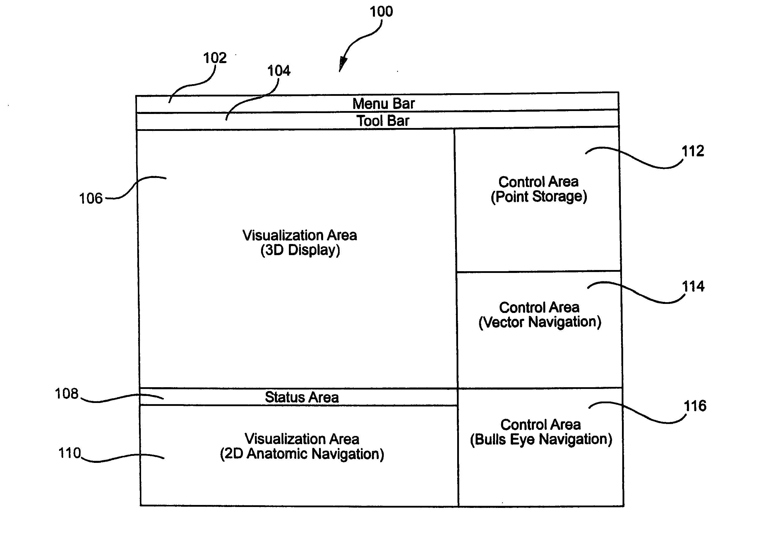
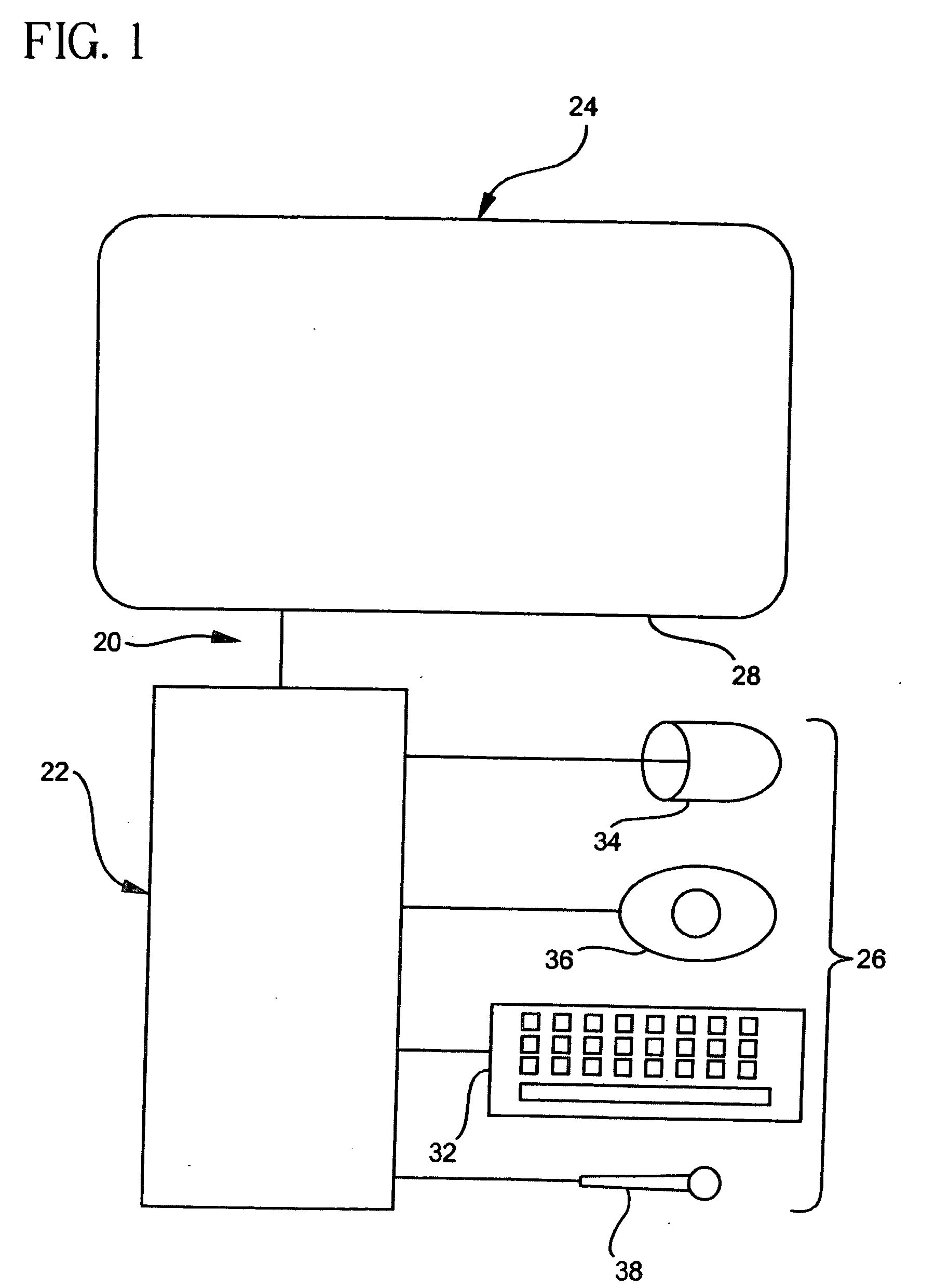
[0156] an interface is illustrated in FIGS. 20-26. The interface is adapted for controlling a magnetic navigation system that applies a magnetic field in a selected direction to an operating region in a subject to magnetically orient a medical device in the operating region. The interface comprises a display 602 on which at least one image of the operating region is displayed, and in this preferred embodiment the display has panes 604 and 606 for displaying images of the operating region from two different planes, to facilitate identifying points in three dimensional space in the operating region. The interface further comprises an input device, such as a mouse (not shown) for identifying points in the operating region on the at least one image on the display, for example by moving a cursor or other indicator over the display, and “clicking” on the selected point. Of course the interface could be any other device for identifying points on the display, including joysticks, touch scre...

fourth embodiment

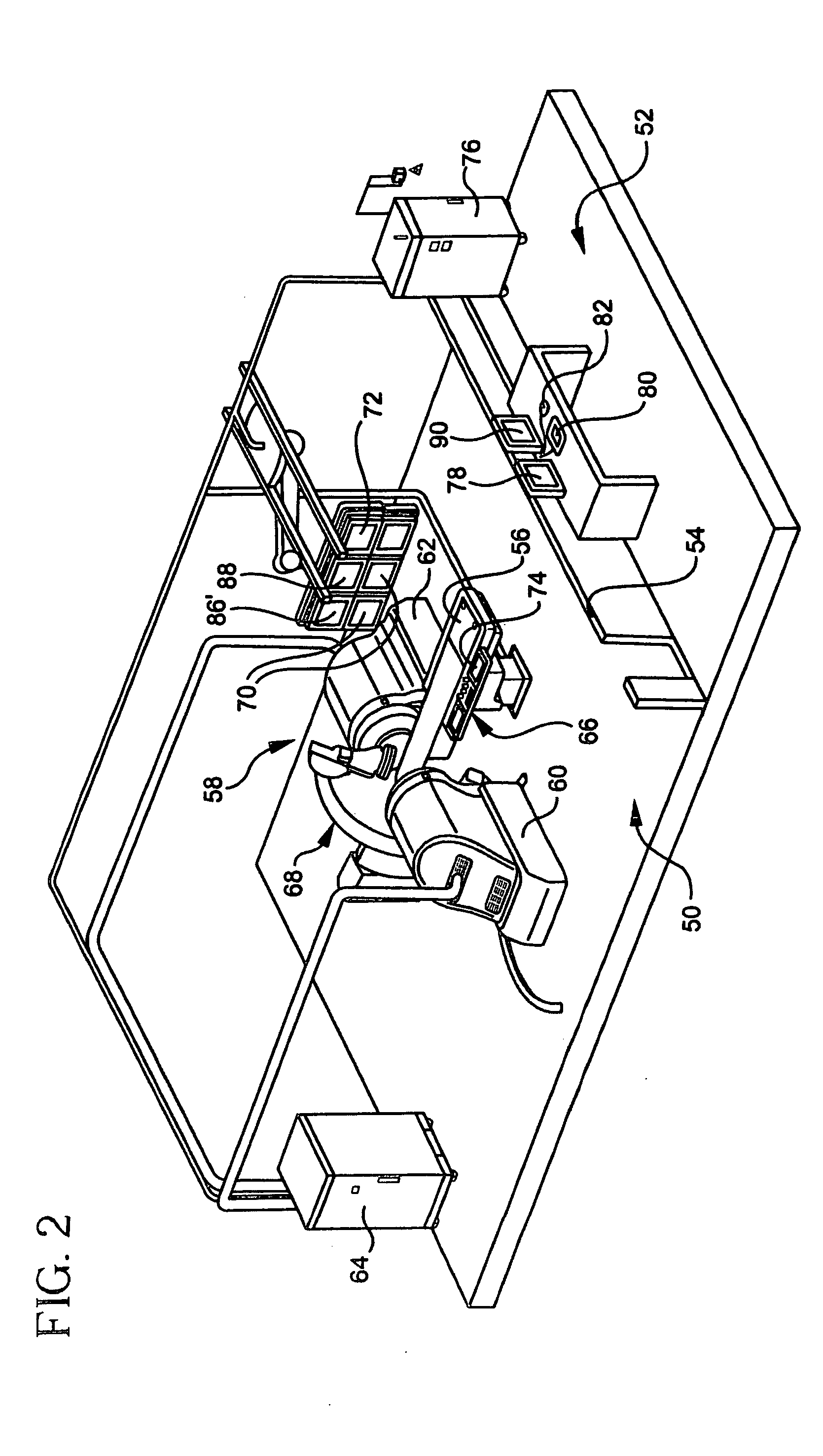
[0178] an interface in accordance with the principles of this invention is illustrated in FIGS. 32-48.

[0179] One possible embodiment of a main menu for display on the monitors 72 and 80 is indicated generally as 700 in FIG. 32. The menu 700 has virtual buttons which the user can select and click using either the mouse 74 or 84, or using the joystick 76 or 86. In this preferred embodiment there are buttons 702 for operating the interface in the basic mode, button 704 for using the interface in an EP procedure; button 106 for using the interface in and IC procedure, and a button 708 for using the interface during a CRT procedure. The menu preferably also has buttons 710 for opening a previous procedure, a button 112 for importing a previous procedure, and a button 714 for exporting a previous procedure, and a button 716 for shutting down the system.

[0180] To enter the basic navigation mode of the interface, a user points the cursor at the “basic” button 702, and clicking with the mou...


PUM


Abstract

An interface for remotely controlling a medical device in a patient's body provides a two dimensional display of a three dimensional rendering of the operating region, and allows the user to select the orientation or location of the distal end of the medical device on the display and then operate a navigation system to cause the distal end of the medical device to approximately assume the selected orientation or location.

Description

CROSS REFERENCE TO RELATED APPLICATIONS [0001] This application claims benefit of U.S. Provisional Application Ser. No. 60 / 576,946, filed Jun. 4, 2004, incorporated herein by reference.BACKGROUND OF THE INVENTION [0002] This invention relates to the remote navigation of medical devices in a patient's body, and in particular to a user interface for controlling a remote navigation system. [0003] Advances in technology have resulted in systems that allow a physician or other medical professional to remotely control the orientation of the distal of a medical device. It is now fairly routine steer the distal end of a medical device inside a patient's body by manipulating controls on the proximal end of the medical device. Recently magnetic navigation systems have been developed that allow a physician to orient the distal end of a medical device using the field of an external source magnet. Other systems have been discussed for the automated remote orientation of the distal end of a medic...

Claims


Application Information

Patent Timeline
Patent Type & Authority Applications(United States)
IPC IPC(8): A61B5/05G06F17/00A61B6/12A61B8/08A61B19/00
CPCA61B6/12A61B6/548A61B19/22A61B19/5225A61B19/5244A61B19/56A61B2019/2253A61B2019/505A61B2019/507A61B2019/5238A61B2019/5251A61B2019/5274A61B2019/5289A61B2019/5458A61B8/0833A61B34/73A61B2034/2074A61B34/20A61B34/70A61B34/25A61B2090/364A61B2090/376A61B2034/105A61B2034/107A61B90/37A61B2034/2051A61B2090/3958
Inventor VISWANATHAN, RAJU R.BLUME, WALTER M.GARIBALDI, JEFFREY M.RAUCH, JOHN
Owner STEREOTAXIS
Why Eureka
Try Eureka