Method and system for substrate temperature profile control

a temperature profile control and substrate technology, applied in vacuum evaporation coatings, chemical vapor deposition coatings, coatings, etc., can solve the problems of uneven heat transfer between the substrate and the substrate holder, the temperature of the substrate holder is not always adequate, and the pressure of the gas is typically not uniform, so as to achieve rapid changes in the temperature of the substrate holder

Inactive Publication Date: 2006-02-09
TOKYO ELECTRON LTD
View PDF4 Cites 45 Cited by
  • Summary
  • Abstract
  • Description
  • Claims
  • Application Information

AI Technical Summary

Benefits of technology

[0010] Still another object of the current invention is to provide rapid changes i

Problems solved by technology

When the backside gas is utilized the pressure of the gas is typically not uniform.
This non-uniformity of pressure of the backside gas can result in uneven heat transfer between the substrate and the substrate holder.
A single temperature control channel in the substrate holder cannot always provide adequate temperature control to ensure the temperature profile of the substrate is at specified levels when backside gas pressure is not

Method used


Image

  • Method and system for substrate temperature profile control
  • Method and system for substrate temperature profile control
  • Method and system for substrate temperature profile control

Examples


Embodiment Construction

[0021] In the following description, in order to facilitate a thorough understanding of the invention and for purposes of explanation and not limitation, specific details are set forth, such as a particular geometry of the substrate holder and various shapes of the temperature control elements in the substrate holder. However, it should be understood that the invention may be practiced in other embodiments that depart from these specific details.

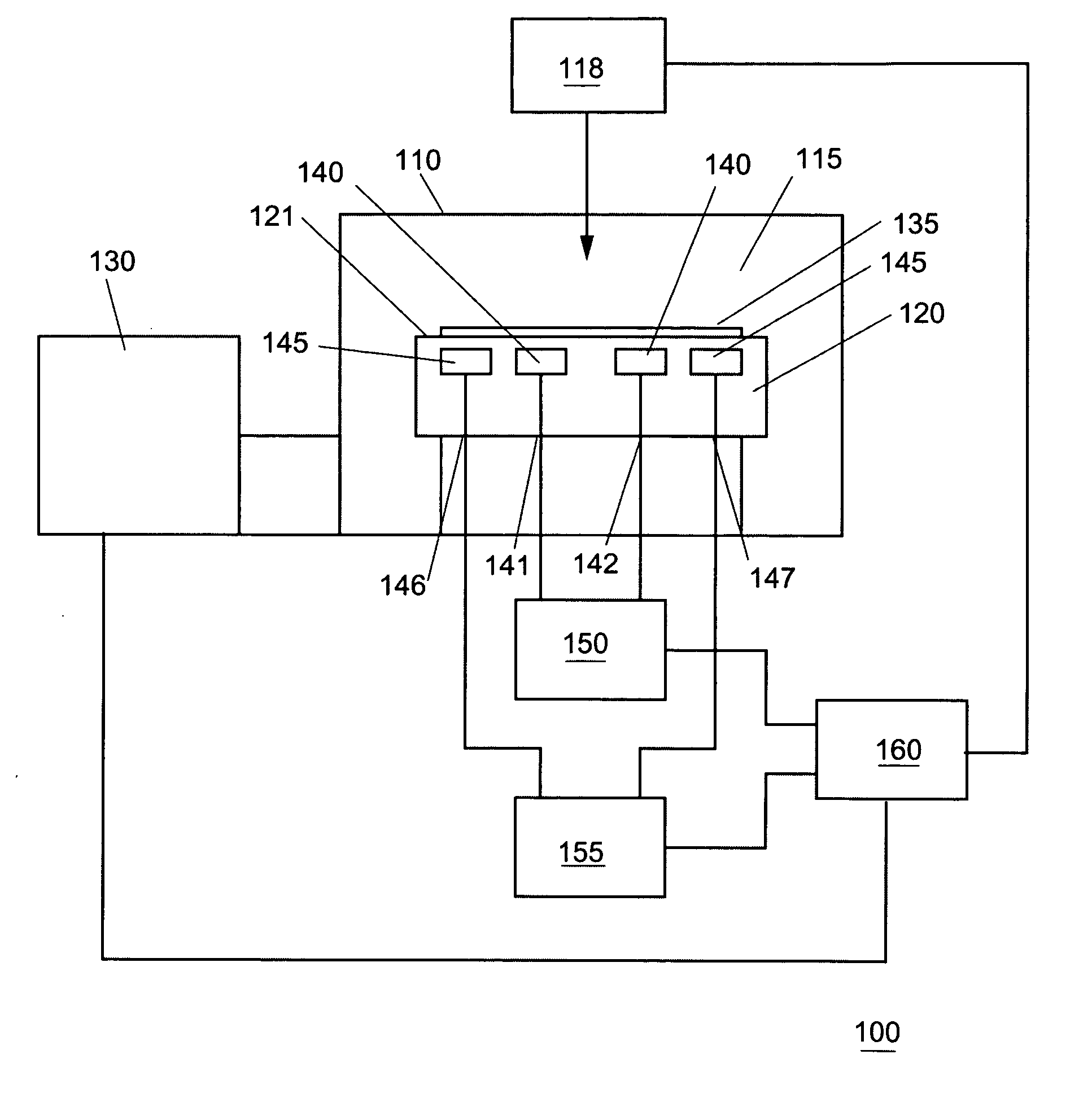
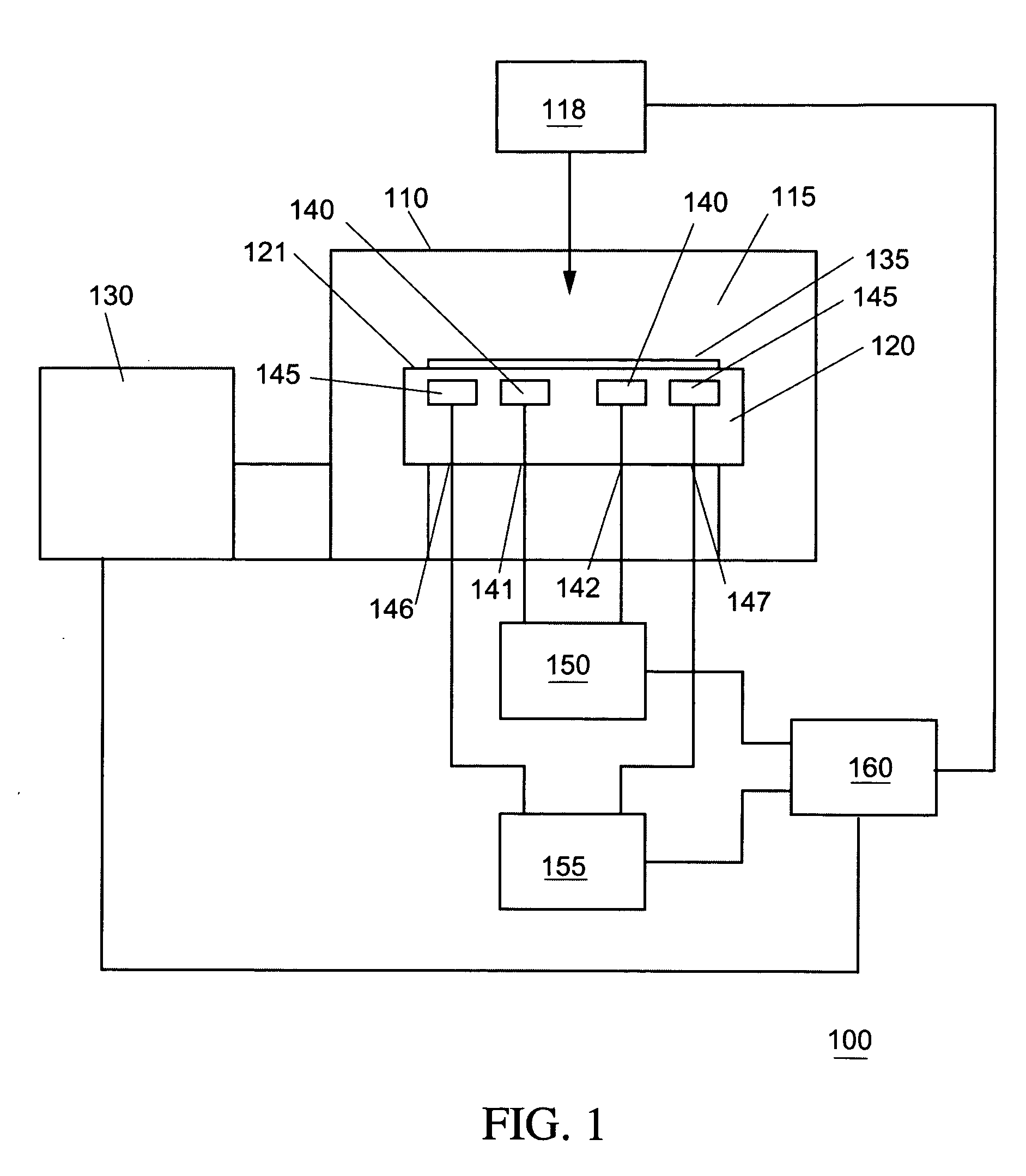
[0022] According to an embodiment of the present invention, a material processing system 100 is depicted in FIG. 1 that includes a process tool 110 having a substrate holder 120 and a substrate 135 supported thereon. The substrate holder 120 is configured to provide at least two thermal zones arranged within the substrate holder 120 in order to provide temperature profile control and / or rapid adjustment of the substrate temperature within the material processing system 100. The thermal zones each can, for example, comprise a fluid channel f...


PUM

PropertyMeasurementUnit
Temperatureaaaaaaaaaa
Flow rateaaaaaaaaaa
Thermal conductivityaaaaaaaaaa

Abstract

A method and system are provided for rapid temperature profile control of the upper surface of a substrate holder providing a specified uniformity or specified non-uniformity of the temperature profile on that surface. The substrate holder includes a first fluid channel positioned in a first thermal zone, utilizing a heat transfer fluid at a specified flow rate and at a specified temperature, to control the temperature profile of the first thermal zone of the surface of the substrate holder. A second fluid channel positioned in a second thermal zone of the substrate holder, utilizing a heat transfer fluid at a specified flow rate and at a specified temperature, is configured to control the temperature profile of the second thermal zone of the surface of the substrate holder.

Description

CROSS REFERENCE TO RELATED APPLICATIONS [0001] The present invention is related to U.S. patent application Ser. No. 10 / 721,500, filed Nov. 14, 2003, U.S. Provisional Application Ser. No. 60 / 458,043, filed Mar. 28, 2003, and U.S. application Ser. No. 10 / 168,544, filed on Jul. 2, 2002, the entire contents of these applications is incorporated herein by reference.FIELD OF THE INVENTION [0002] The present invention relates to a method and system for temperature profile control of a substrate, and more particularly to a substrate holder for temperature profile control of a substrate. BACKGROUND OF THE INVENTION [0003] It is known in semiconductor manufacturing and processing that various processes, including for example etch and deposition processes, depend significantly on the temperature of the substrate. For this reason, the ability to uniformly control the temperature of a substrate is an essential requirement of a semiconductor processing system. The temperature of a substrate is de...

Claims


Application Information

Patent Timeline
IPC IPC(8): C23C16/00
CPCC23C14/541C23C16/46C23C16/4586
Inventor TSUKAMOTO, YUJIMOROZ, PAULIWAMA, NOBUHIROHAMAMOTO, SHINJI
Owner TOKYO ELECTRON LTD
Why Eureka
Try Eureka