
Apparatus for initiating and dispensing an incendiary

a technology for incendiary and dispenser, which is applied in the field of incendiary dispenser, can solve the problems of low reliability of incendiary dispenser, sphere jamming, and risk of combustion within the chute itsel

Inactive Publication Date: 2006-02-09
RAINDANCE SYST
View PDF26 Cites 19 Cited by
  • Summary
  • Abstract
  • Description
  • Claims
  • Application Information

AI Technical Summary

Benefits of technology

[0012] Preferably said drive system is coupled to said injection device for moving said injection device between an extended position where said injection device penetrates said incendiary, and a retracted position where said injection device is spaced from said incendiary.
[0013] Preferably said drive system is coupled to said cutter for moving said cutter between an extended position where said cutter cuts an incendiary from said line and a retracted position where said cutter is spaced from said line.

Problems solved by technology

This combination of incendiary and dispenser have low reliability.
This is in part due to difficulties in sequentially feeding the spheres to a chute and then successfully injecting them with glycol.
It is not uncommon for the spheres to become jammed in the chute which then requires manual clearing.
If the clearing is not performed expeditiously, there is a risk of combustion occurring within the chute itself.
Another reason for the relatively low reliability is the sealing of the holes through which the spheres are initially loaded with potassium permanganate with wax or hot glue.
If the spheres are orientated so that the needle injecting the glycol is aligned with the wax or glue, the needle can become blocked and has to be removed and cleaned before further use.
Also, sometimes the needle hits the join and crushes the sphere.

Method used


Image

  • Apparatus for initiating and dispensing an incendiary
  • Apparatus for initiating and dispensing an incendiary
  • Apparatus for initiating and dispensing an incendiary

Examples


Embodiment Construction

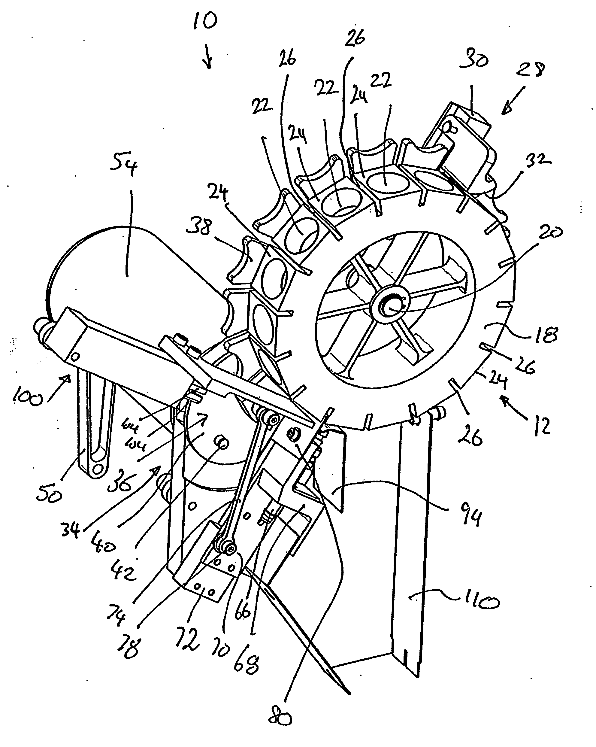
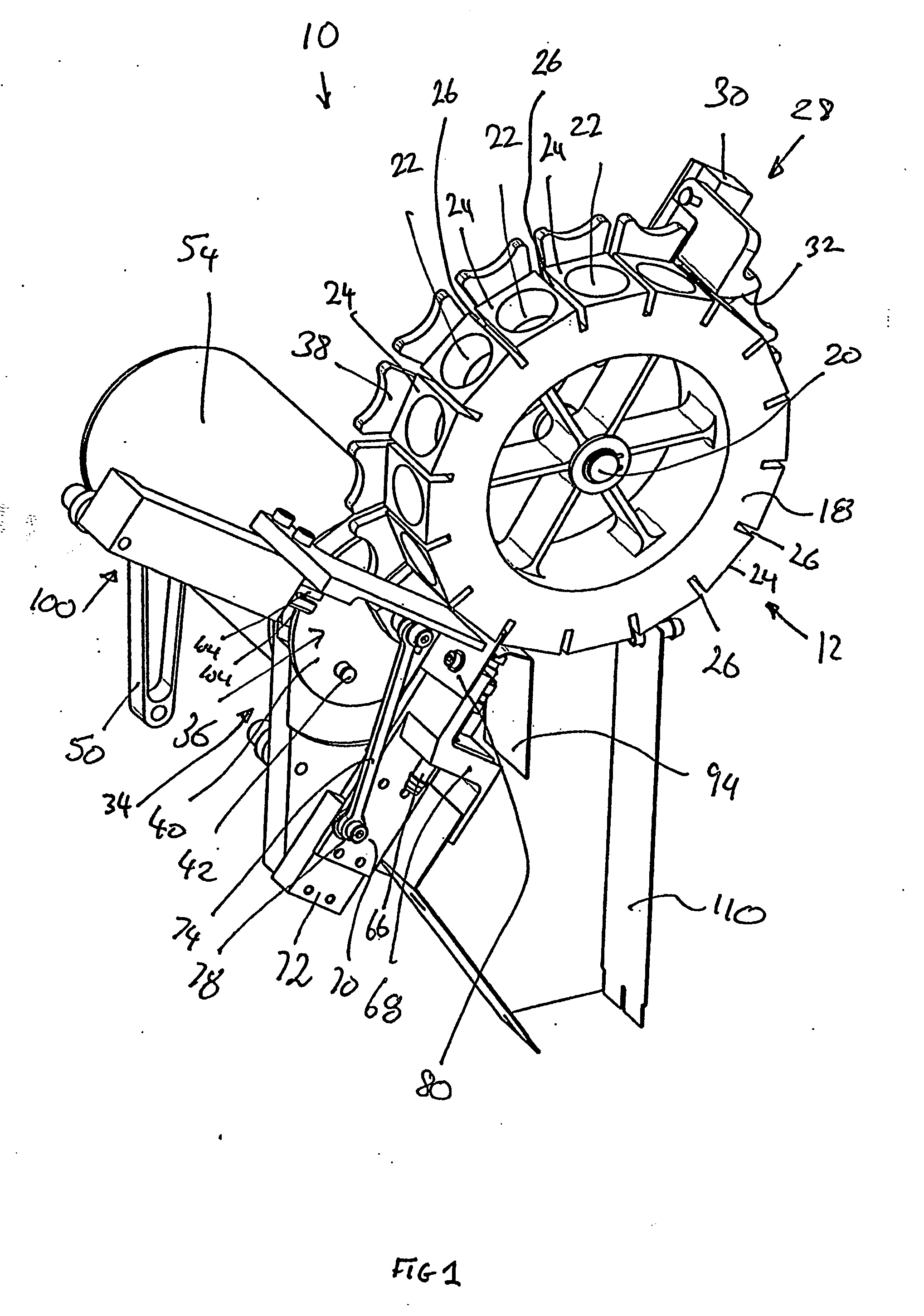
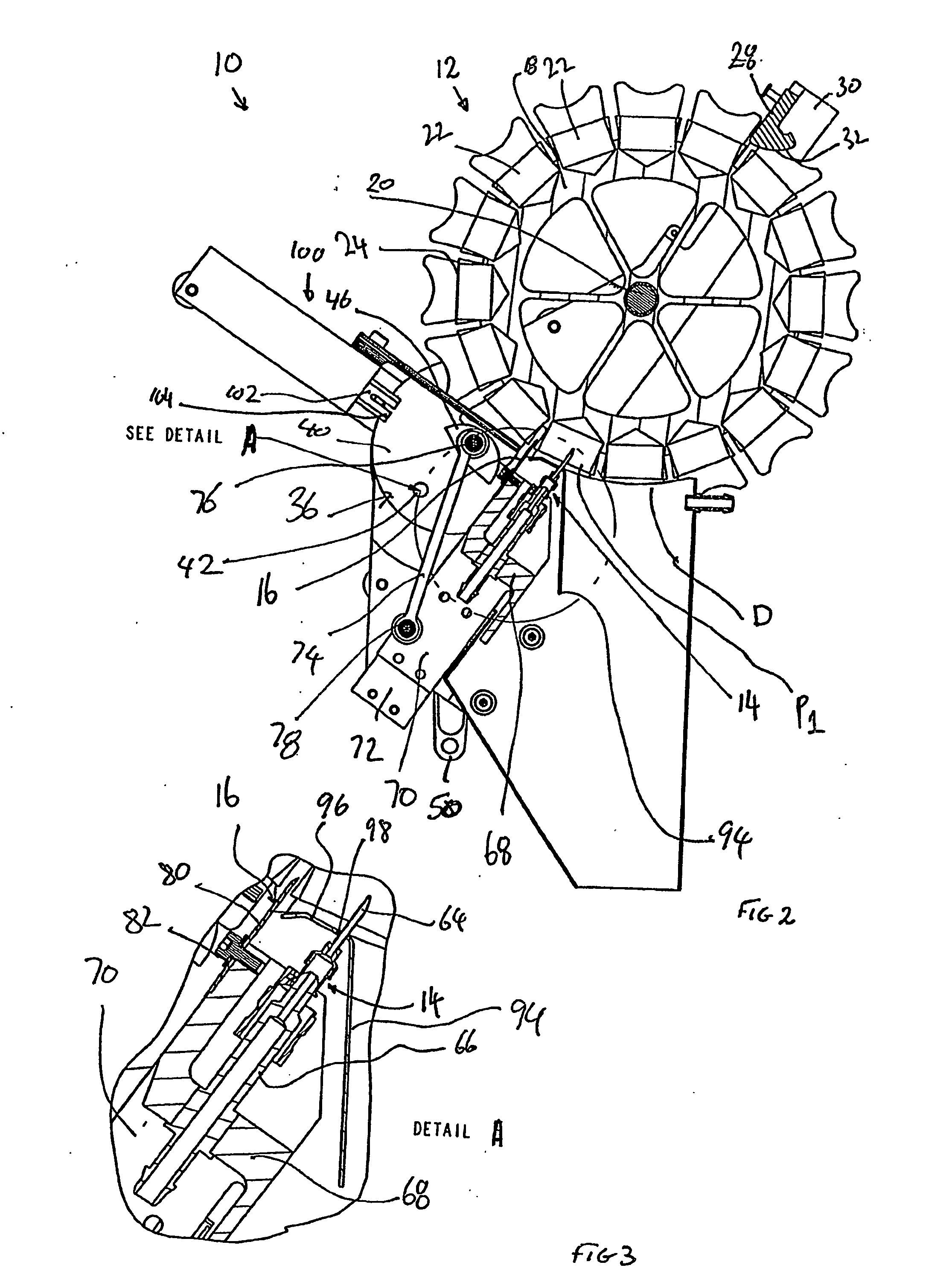
[0051] Referring to the accompanying drawings, and in particular FIGS. 1-3, it is seen that an apparatus 10 for initiating and dispensing an incendiary capsule 212 (FIGS. 9-16) from a belt or line 210 of series connected incendiaries comprises a feed mechanism 12 for advancing the incendiary belt to a dispensing location D; an injection device 14; and a cutter 16. The feed mechanism 12 in this embodiment advances the line of incendiaries in an anti-clockwise direction to the location D which is at approximately the six o'clock position. The injection device 14 injects a substance such as glycol into an incendiary 212 as the incendiary belt 210 is moved toward, but prior to reaching, the dispensing location D. The glycol reacts exothermically with another substance such as potassium permanganate 214 in the incendiary 212. The cutter 16 cuts the incendiary 212 into which the glycol has been injected from the belt 210. After the incendiary 212 has been injected with the glycol and cut ...


PUM


Abstract

An apparatus (10) for initiating and dispensing an incendiary comprises a feed mechanism (12) for advancing a line of series connected incendiaries to a dispensing location D; an injection device (14); and a cutter (16). The injection device (14) injects a substance such as glycol into the incendiary as it is moved toward, but prior to reaching, the dispensing location D. The glycol reacts exothermically with another substance such as potassium permanganate in the incendiary. The cutter (16) cuts the incendiary into which the glycol has been injected from the line of series connected incendiary. After the incendiary has been injected with the glycol and cut by the cutter (16) from the line, the feed mechanism (12) advances the incendiary to the dispensing location D where it is dispensed by the action of gravity from the apparatus (10).

Description

FIELD OF THE INVENTION [0001] The present invention relates to an apparatus for initiating and dispensing an incendiary, and in particular, but not exclusively, for use in airborne fire control procedures such a backburning. BACKGROUND OF THE INVENTION [0002] It is known to drop incendiaries from helicopters and light aircraft for the purposes of forestry management and back burning. One known incendiary is in the form of a small sphere (of approximately 32 mm diameter) of plastics material filled with a quantity of potassium permanganate granules or powder. Each sphere is formed from two hemispheres injection moulded from extruded plastic and subsequently joined together. A small hole is formed in the sphere to allow filling with a volume of potassium permanganate. The hole is then sealed with wax (hot glue). These spheres are usually dropped from a semi-automatic dispenser provided with a hopper for holding a large number of spheres and which feeds the spheres sequentially to a ch...

Claims


Application Information

Patent Timeline
Patent Type & Authority Applications(United States)
IPC IPC(8): A62C3/00A62C3/02A62C99/00B64D1/04
CPCA62C3/0285A62C99/0054F42B12/44F41B4/00B64D1/04
Inventor STEVENSON, ROBERTHANBURY, PETER
Owner RAINDANCE SYST
Learn More