Integrated real-time automated location positioning asset management system

a real-time, asset management system technology, applied in the direction of instruments, electric signalling details, mechanical actuation of burglar alarms, etc., can solve the problems of inconvenient use, difficult techniques, and inability to automate identification systems, and achieves significant signal strength advantages, low or no power, and cheap and effective ways

Active Publication Date: 2006-02-09
AVAYA INC
View PDF56 Cites 109 Cited by
  • Summary
  • Abstract
  • Description
  • Claims
  • Application Information

AI Technical Summary

Benefits of technology

[0014] In one configuration, devices in the vicinity of a communication device contain or include a passive, semi-passive, or active RFID tag enabling them to be detected by the RFID reader in communication with the communication device and reported to the monitoring server. This configuration enables non-networked objects, such as computer monitors, computers, and telephony headsets, to be managed via the enterprise communications network where up-to-date information is relayed. The non-networked objects are fitted with RFID tags, which the RFID reader can identify. The RFID tags can be inexpensive and require little or no power. With communication devices usually spread around a building, this configuration can provide a cheap and effective way to obtain near 100% coverage of the building. It also enables monitoring of equipment in real-time, even if the equipment is moved. As all communication devices have power, they can provide an ideal place for the RFID reader. This is one of the main reasons why active RFID-type devices are not used as commonly as passive devices, though they offer a significant signal strength advantage. The configuration can also provide accurate tracking in real time using a combination of “fixed” devices. If an RFID tag is detected by multiple readers, triangulation techniques can be used to pinpoint a

Problems solved by technology

Automatic identification systems can have disadvantages.
For equipment that is on the floor, under desks, behind monitors, and the like, these techniques can be difficult and require personnel to collect physically the desired information.
Use of manual scanners are also slow and practically impossible to maintain current asset location information.
Moreover, Local Area Networks or LAN's for automatic identification systems are not widely us

Method used


Image

  • Integrated real-time automated location positioning asset management system
  • Integrated real-time automated location positioning asset management system
  • Integrated real-time automated location positioning asset management system

Examples


Embodiment Construction

[0022] The invention will be illustrated below in conjunction with an exemplary communication system. Although well suited for use with, e.g., a system having a private branch exchange (PBX) or other similar contact processing switch or server, the invention is not limited to use with any particular type of communication system switch or server or configuration of system elements. Those skilled in the art will recognize that the disclosed techniques may be used in any communication application in which it is desirable to provide improved contact processing directed from an external network into a PBX or other communication system switch or server.

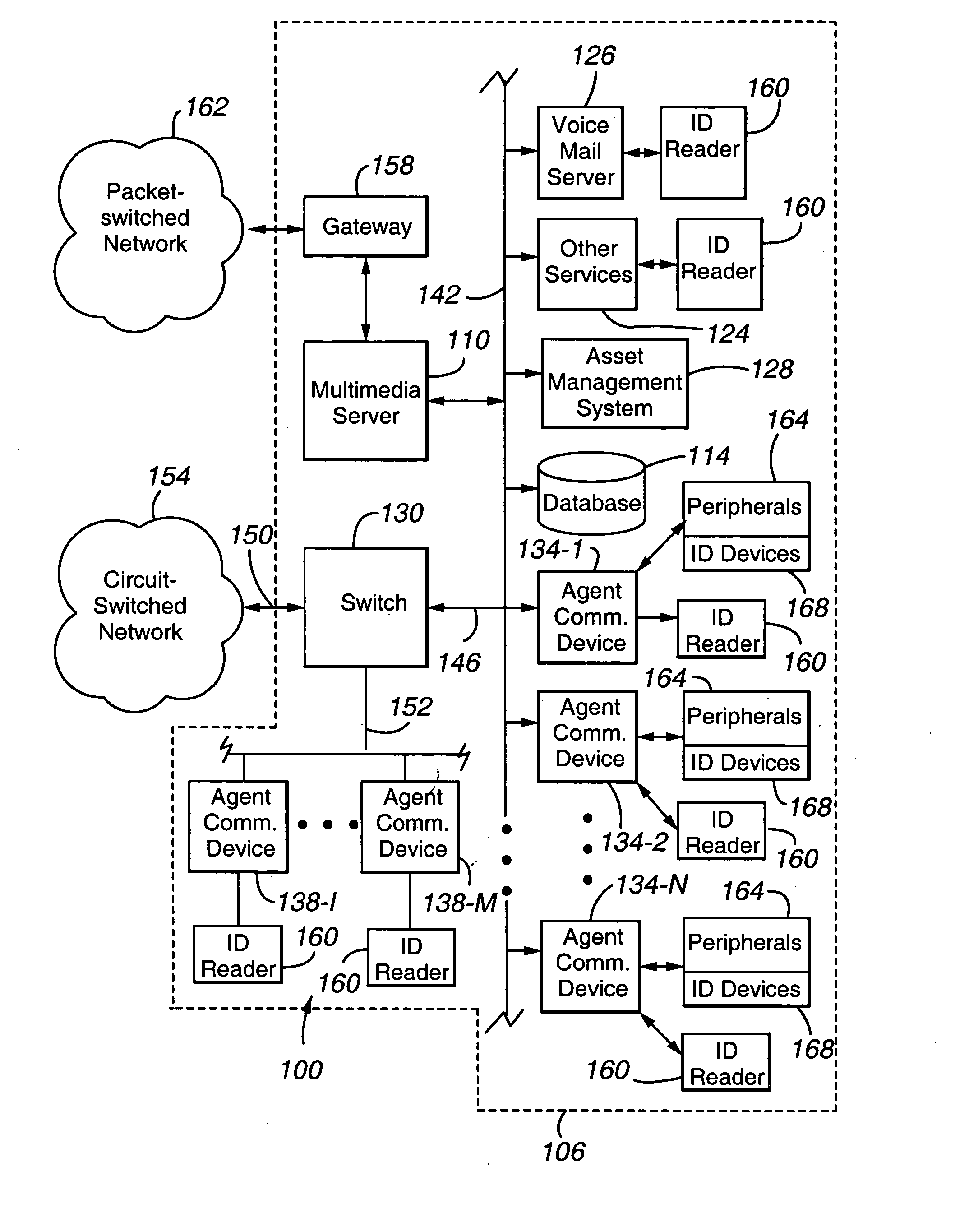
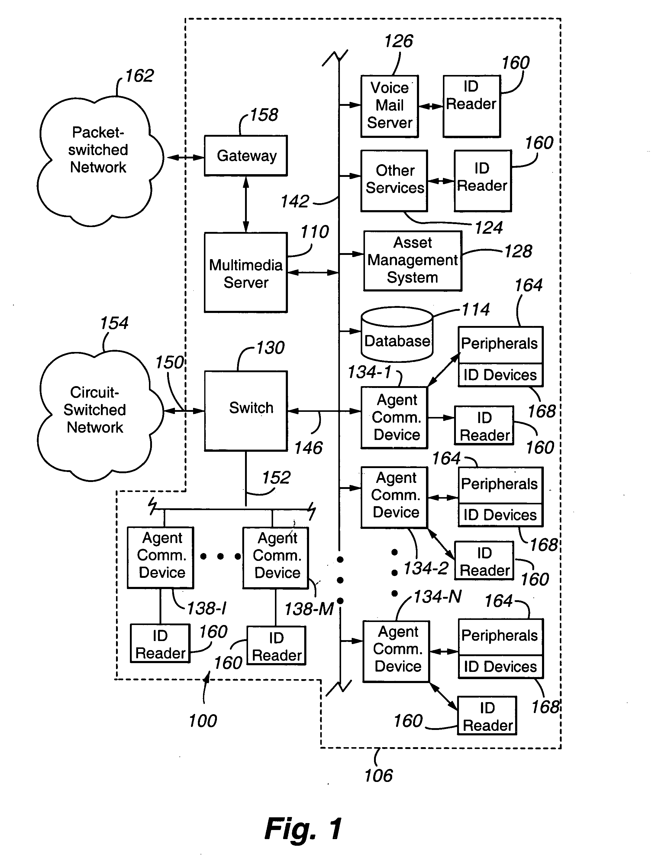
[0023]FIG. 1 shows an exemplary communication system 100 in which the invention is implemented. The system 100 includes a multi-media server 110 that serves a premises 106, including circuit-switched communication devices 138-1, . . . 138-M that are subscribers to the server 102, a Local Area Network 142 that serves a number of communicati...


PUM


Abstract

An enterprise network 100 for tracking objects is provided. The network 100 includes: (a) a plurality of subscriber communication devices 134 and 138; (b) a plurality of readers 160, each of the communication devices being in communication with a corresponding reader, wherein each reader is operable to read a set of object identifiers, each object identifier in the set corresponding to an Identification device 168 positioned on a respective object 164; and (c) a location agent 324 operable to determine, from at least one of the sets of object identifiers, a physical location of each object 164 having an object identifier in the at least one of the sets of object identifiers.

Description

CROSS REFERENCE TO RELATED APPLICATION [0001] Cross reference is made to U.S. patent application Ser. Nos. 10 / 795,119, filed Mar. 5, 2004, entitled “Advanced Port-Based E911 Strategy for IP Telephony” and Ser. No. 10 / 607,414, filed Jun. 25, 2003, entitled “Universal Emergency Number ELIN Based on Network Address Ranges”, each of which is incorporated herein by this reference.FIELD OF THE INVENTION [0002] The invention relates generally to object tracking and particularly to object tracking using a communications network. BACKGROUND OF THE INVENTION [0003] Automatic identification systems, such as asset management and security systems, are becoming increasingly important in the workplace of today. Automatic identification systems refer to a host of technologies used to assist machines in identifying objects, such as assets and people. Automatic identification is typically coupled with data capture. In other words, companies want to identify items, capture information about the object...

Claims


Application Information

Patent Timeline
IPC IPC(8): G08B5/22G06Q30/00G08B1/08G08B13/14G06Q10/00H04W24/00H04W64/00H04W84/10H04W84/12
CPCG06Q10/087G06Q10/00
Inventor MCNAMARA, PAUL THOMASMINHAZUDDIN, MUNEYBFEGAN, CHRISTOPHER ALEXANDERLENARD, ROHANWARTA, RALPH
Owner AVAYA INC
Why Eureka
Try Eureka