Display module housing

a technology for display modules and housings, applied in non-linear optics, instruments, optics, etc., can solve the problems of reducing the reliability of display modules b>100/b>, unable to effectively fasten flat display panels, etc., and achieves the effect of reducing the stickiness of fixing glue and shock resistan

Inactive Publication Date: 2006-02-09
INNOCOM TECH SHENZHEN +1
View PDF3 Cites 29 Cited by
  • Summary
  • Abstract
  • Description
  • Claims
  • Application Information

AI Technical Summary

Benefits of technology

[0007] It is therefore a primary objective of the present invention to provide a display module housing having a particular fastening device, so that the function of fixing glue for fastening the display panel used in the prior art can be enhanced or substituted, and the inability to fasten the display panel due to the reduction in stickiness of the fixing glue can be solved.
[0009] Since the display module housing of the present invention is provided with a fixing mechanism and a flexible fastening device, the display panel may be clipped and immobilized in the display module housing, and no additional fixing glue is required to be adhered thereto. Thus, the prior art problem of the reduced stickiness of the fixing glue, which causes the display panel to warp upwards and separate from the housing, can be solved to make the display module housing more shock-resistant.

Problems solved by technology

Therefore, the flat display panel 102 may not be effectively fastened, and the reliability of the display module 100 may thus be reduced.

Method used


Image

  • Display module housing
  • Display module housing
  • Display module housing

Examples


second embodiment

[0020] Please refer to FIG. 4. FIG. 4 is a schematic diagram of a display module housing 50 of the second embodiment according to the present invention. The display module housing 50 comprises a frame structure 52, a fixing mechanism 54, two flexible fastening devices 56, and a bottom plate 58. As shown in FIG. 4, the frame structure 52 is formed in conjunction with the bottom plate 58 to form a holding space 60 which can accommodate a display panel. In addition, the frame structure 52 has discontinuous sidewalls. As shown in FIG. 4, on the front and back side of the frame structure 52 possess only a part of the sidewall 52a, which provides the function of preventing the display panel placed in the holding space 60 from sliding forwards and backwards. The fixing mechanism 54 has a strip clasping structure protruding to the topside surface of the sidewall 52a of the frame structure 52, and works in association with the two flexible fastening devices 56 to clip and immobilize the surf...

third embodiment

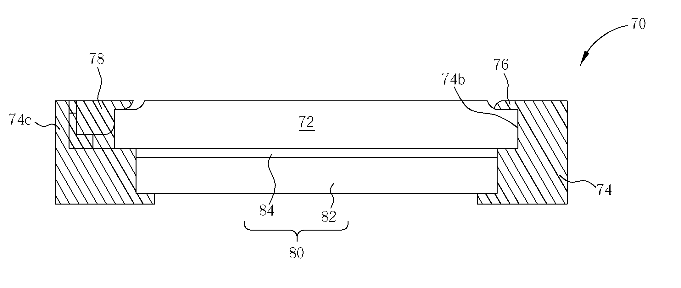
[0021] Please refer to FIG. 5 and FIG. 6. FIG. 5 is a schematic diagram of a display module housing 70 of a third embodiment according to the present invention, while FIG. 6 is a cross-sectional view of the display module housing 70 accommodating a display panel 72 shown in FIG. 5. The display module housing 70 comprises a frame structure 74, a fixing mechanism 76, and a flexible fastening device 78. The frame structure 74 has four sidewalls 74a, 74b, 74c, and 74d, warping together to form a rectangular framework, and thus forming a holding space 86 for accommodating the display panel 72, wherein the display panel 72 is a liquid crystal display panel. The fixing mechanism 76 is a strip cover plate, protruding to the sidewall 74b of the frame structure 74, and is formed in conjunction with the sidewalls 74a and 74d of the frame structure 74. As shown in FIG. 6, the fixing mechanism 76 covers the edge surface in one side of the display panel 72 to immobilize the display panel 72 to th...


PUM

PropertyMeasurementUnit
flexibleaaaaaaaaaa
temperatureaaaaaaaaaa
humidityaaaaaaaaaa

Abstract

A display module housing for fixing a display panel comprises a frame structure, at least a fixing mechanism, and at least a flexible fastening device disposed on the topside of the sidewall of the frame structure. When the display panel is positioned in the frame structure, the fixing mechanism and the flexible fastening device clip the display panel so that the display panel is fixed in the display module housing.

Description

BACKGROUND OF INVENTION [0001] 1. Field of the Invention [0002] The present invention provides a display module housing, more specifically, a display module housing with specific fastening devices. [0003] 2. Description of the Prior Art [0004] With the rapid development of technology, various kinds of intelligent information products are available to people living in modern societies. For example, flat display modules, such as liquid crystal display modules, etc., have played quite an important role in information products. Since the flat display module has the characteristics of a light and portable configuration, low power consumption, no radiation pollution, and so on, it has been widely applied to portable information products, such as notebooks, personal digital assistants (PDAs), and cellular phones, etc. There is even a trend of gradually replacing the CRT monitor of conventional personal computers and CRT TVs with the flat display module. [0005] Please refer to FIG. 1. FIG. ...

Claims


Application Information

Patent Timeline
Patent Type & Authority Applications(United States)
IPC IPC(8): G02F1/1333
CPCG02F2201/465G02F1/133308
Inventor CHOU, MING CHUAN
Owner INNOCOM TECH SHENZHEN
Why Eureka
Try Eureka