Image sensor with device for adjusting focus

a focus adjustment and image sensor technology, applied in the field of image sensors, can solve the problems of reduced yield rate, complicated scanner configuration, and low focus tolerance of the optical system, and achieve the effect of high quality scanning performance and precise focusing

Active Publication Date: 2006-02-09
ATEN INT CO
View PDF13 Cites 9 Cited by
  • Summary
  • Abstract
  • Description
  • Claims
  • Application Information

AI Technical Summary

Benefits of technology

[0009] Another object of the present invention is to provide a focus adjusting device for an image sensor that compensates for the gross tolerance of the image sensor and thus ensures high quality scanning performance for various kinds of objects being scanned.
[0010] To achieve the above objects of the present invention, an image sensor in accordance with the present invention comprises a sensing substrate with image sensing elements disposed thereon, a light source for illuminating the object being scanned, a lens for gathering the light reflected from the object being scanned and focusing the reflected light on the image sensing elements of the sensing substrate, a housing for housing the above components, and two focus adjusting devices provided at respective opposite ends of the housing. The focus adjusting devices are adapted to adjust the focus of the optical system of the image sensor so that precise focusing can be ensured. Each focus adjusting device includes a contact element in direct contact with the bottom of a scanner cover plate and a focus fine adjusting element movably mounted on the housing. The contact element is moved along with the movement of the focus fine adjusting element, whereby the distance between an upper surface of the housing and the bottom of the cover plate is thus changed to implement focus adjustment.
[0013] The provision of a focus adjusting device on the present image sensor ensures precise focusing and thus high quality scanning performance by movement activities between the active and passive components of the focus adjusting device.

Problems solved by technology

The transparent objects, such as film-based 35 mm slides or negatives, necessitate complicated scanner configurations and high optical resolution requirements.
High resolution requires low focus tolerance of the optical system.
This results in reduced yield rate and increased production cost, and also focus adjusting cannot be implemented.
It is clear that this method complicates the configuration of the end product and the focus adjusting method, and thus has a negative effect on production efficiency and cost.

Method used


Image

  • Image sensor with device for adjusting focus
  • Image sensor with device for adjusting focus
  • Image sensor with device for adjusting focus

Examples


first embodiment

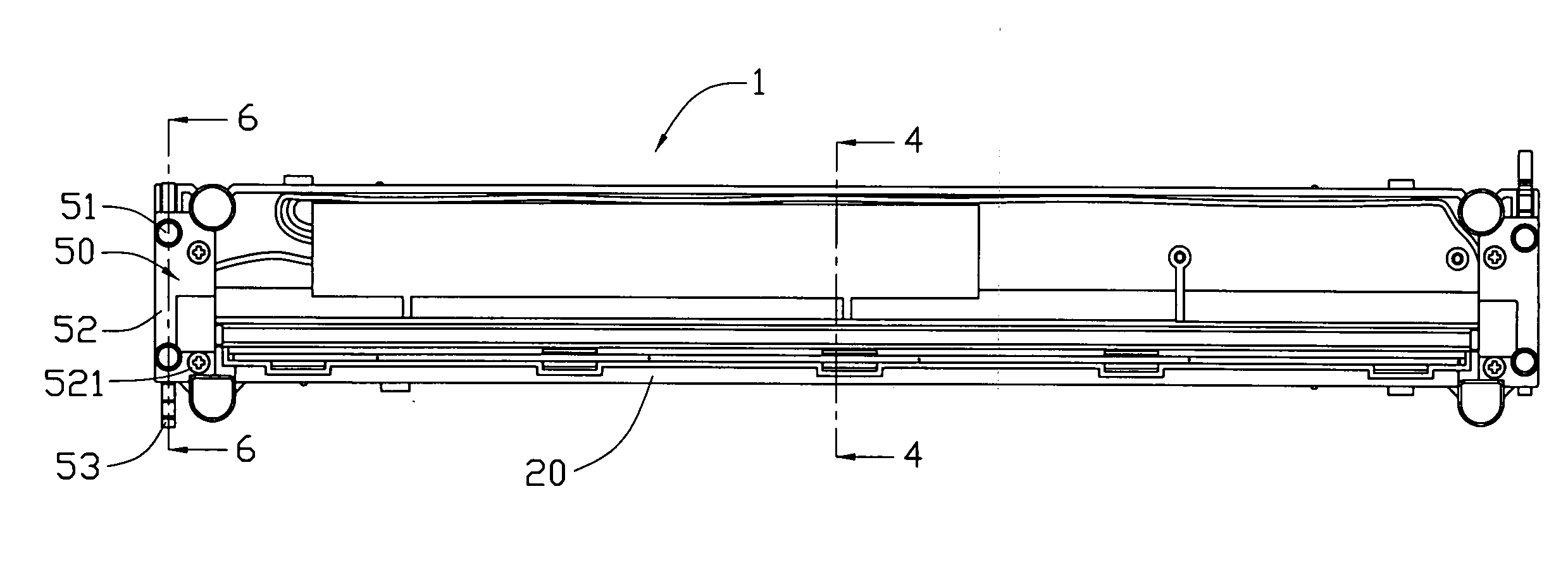
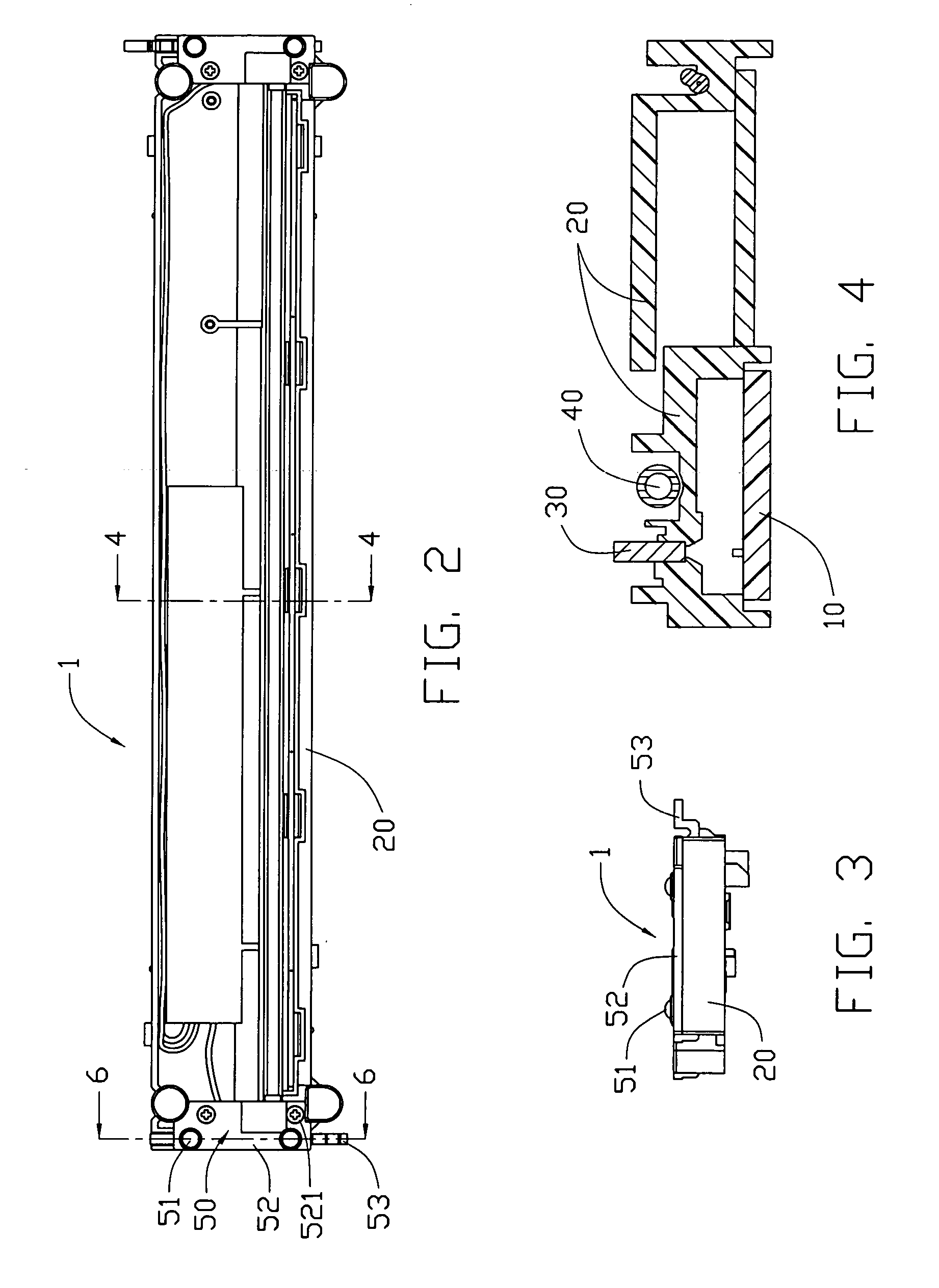
[0027] Also referring to FIGS. 5-7, it is shown that a focus adjusting device 50 in accordance with the present invention is provided at each end of the housing 20 for adjusting the distance between an upper surface of the housing 20 and the bottom of a scanner cover plate (not shown) or the object to be scanned. The focus adjusting device 50 includes a contact element 51, a focus varying mechanism and a focus fine adjusting mechanism. The focus varying mechanism is used to change the focus of the image sensor 1 corresponding to the kind of the object to be scanned. However, no matter what kind of object is to be scanned, precise focusing is the key for good image. This is particularly true when a focus varying mechanism is used. The inevitable accumulated tolerance of the components may cause the problem of out of focus, which must be corrected by a focus fine adjusting mechanism while bringing no increase in production cost and manufacturing precision of the components. The contac...

second embodiment

[0034]FIG. 8 illustrates a focus adjusting device 60 for an image sensor 1 in accordance with the present invention. The focus adjusting device 60 is mounted at each end of the housing 20 of the image sensor 1, and comprises an active element 61, a passive element 62 and an auxiliary element 63 between the active element 61 and the passive element 62. The active element 61 is a slotted screw, the bottom of which is slotted for manual rotation and a top portion of which is engaged with a bottom portion of the auxiliary element 63. The passive element 62 is a block and has two protrusions 620 upwardly projecting from an upper surface thereof for contacting with the lower surface of a scanner cover plate. An inclined surface 621 is provided on the passive element 62 connecting with a bottom surface of the passive element 62. The inclined surface 621 abuts against an inclined surface 630 on the auxiliary element 63. When the slotted screw 61 is rotated, the auxiliary element 63 is corre...

third embodiment

[0035]FIG. 9 illustrates a focus adjusting device 70 for an image sensor 1 in accordance with the present invention. The focus adjusting device 70 includes an active element 71 and a passive element 72. The active element 71 is in the form of a pair of cams, and the passive element 72 is in the form of a pair of rods. The top of the rod 72 is adapted to directly contact with the lower surface of a scanner cover plate, and the bottom of the rod 72 is engaged with the cam 71. When the cam 71 is rotated, the bottom of the rod 72 is guided along the contour of the cam 71, whereby the rod 72 is moved upwards and downwards for focus adjusting.


PUM


Abstract

A focus adjusting device (50) for an image sensor (1) is provided for ensuring precise focusing of the image sensor. The focus adjusting device includes a contact element (51) in direct contact with the bottom of a scanner cover plate, a focus varying element (53) engaging with the contact element, and a focus fine adjusting element (55) movably mounted on a housing of the image sensor. The focus varying element and the contact element are driven to correspondingly move vertically together with the vertical movement of the focus fine adjusting element, whereby the distance between an upper surface of the housing and the bottom of the cover plate is thus changed for precise focusing.

Description

BACKGROUND OF THE INVENTION [0001] 1. Field of the Invention [0002] The present invention relates to an image sensor for reading an image document or the like, and particularly relates to an image sensor with a focus adjusting device. [0003] 2. Description of Prior Art [0004] Image sensors are used to read an image document and convert the image document into an electric signal in image scanners, facsimile machines, or the like. The image sensors that are available at present are roughly classified into two types, i.e., an optical image sensor having a size-reduction optical system including lenses for focusing an image document at a reduced scale onto a CCD (charge-coupled device) to read the image document, and a contact image sensor (CIS) having a sensor unit composed of a plurality of sensor elements formed according to a thin-film fabrication process on an insulating substrate which has a width greater than the width of an image document to be read, the sensor unit being held i...

Claims


Application Information

Patent Timeline
Patent Type & Authority Applications(United States)
IPC IPC(8): H04N1/40G03B13/00H04N1/031H04N3/26
CPCH04N1/02409H04N1/0318H04N2201/03145H04N2201/03112H04N2201/03141H04N2201/02497
Inventor CHI-SHENG, LINYU-LING, WANG
Owner ATEN INT CO
Why Eureka
Try Eureka