Method and system for encoding and detecting optical information

a technology of optical information and optical data, applied in the field of optical data storage, can solve the problems of limiting the amount of data storage that can be supplied in a given data media, negatively affecting the ultimate data reading rate, and ultimately limited data storag

Inactive Publication Date: 2006-02-09
POLARIZONICS CORP
View PDF18 Cites 20 Cited by
  • Summary
  • Abstract
  • Description
  • Claims
  • Application Information

AI Technical Summary

Problems solved by technology

The use of a binary pattern simplifies the detection and proper translation of the mark, but it also limits the amount of data storage that can be supplied in a given data media.
Furthermore, the use of a binary pattern negatively impacts the ultimate data reading rate.
Data storage is ultimately limited by the size of the mark, and the ability to differentiate between adjacent marks.
Increased density is available by utilizing a blue light laser source having a shorter wavelength than the commonly utilized red light laser source, however this results in increased costs.
Furthermore, the use of a blue light laser source does not optimize storage on a given media, since the use of a binary coding method places a limitation on the amount of data that may be stored.
Unfortunately, in practice the use of multi-level encoding has been found to be somewhat difficult, and has not satisfactorily maximized the storage on the optical media.
Unfortunately, this has not been commercially successful, at least partially due to the difficulty in obtaining good resolution.
Unfortunately, only a limited selection of materials having the appropriate photo-induced birefringence which is retained is available.
Unfortunately, resolution based on light intensity is difficult and has not been commercially successful.

Method used


Image

  • Method and system for encoding and detecting optical information
  • Method and system for encoding and detecting optical information
  • Method and system for encoding and detecting optical information

Examples


Embodiment Construction

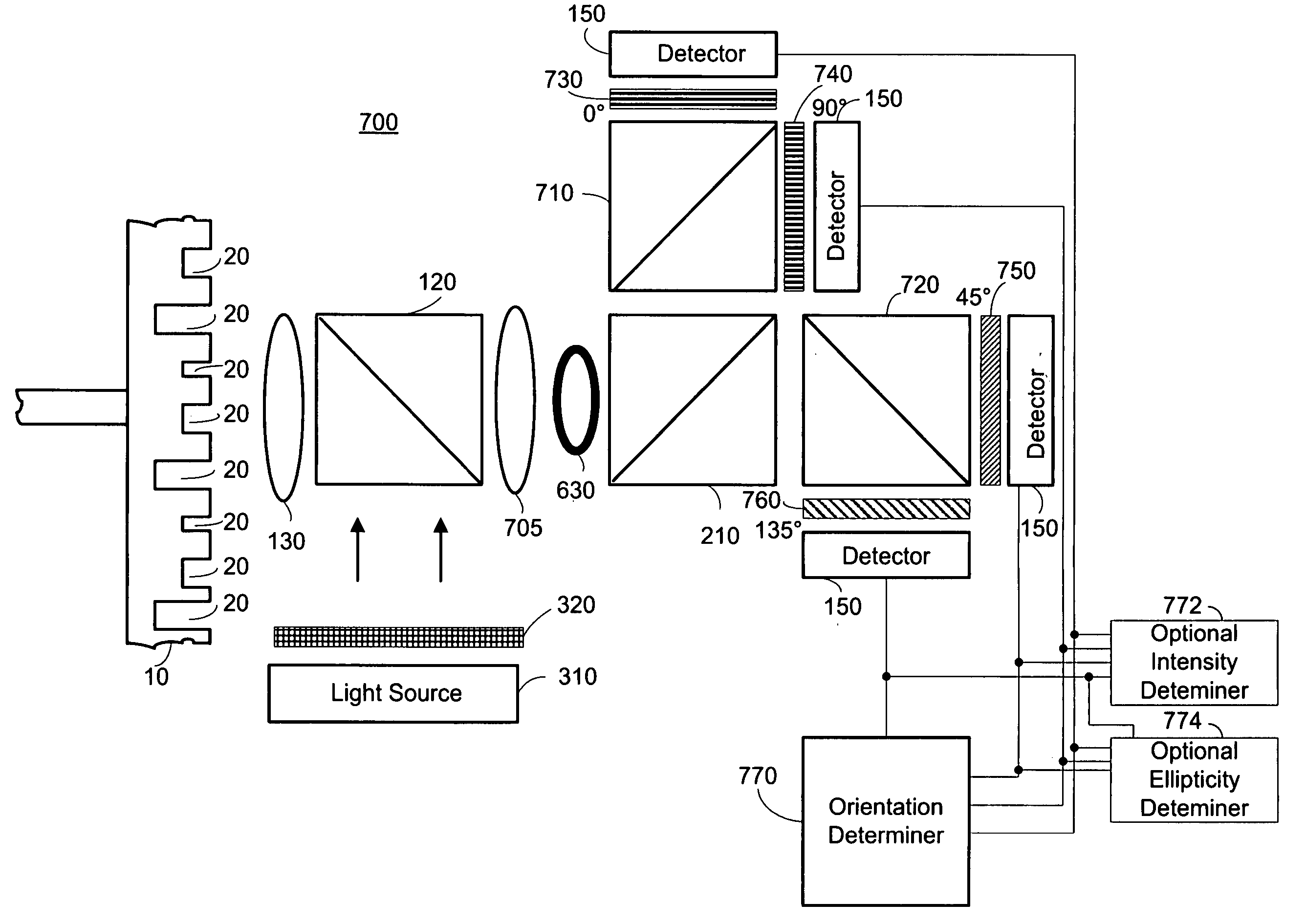
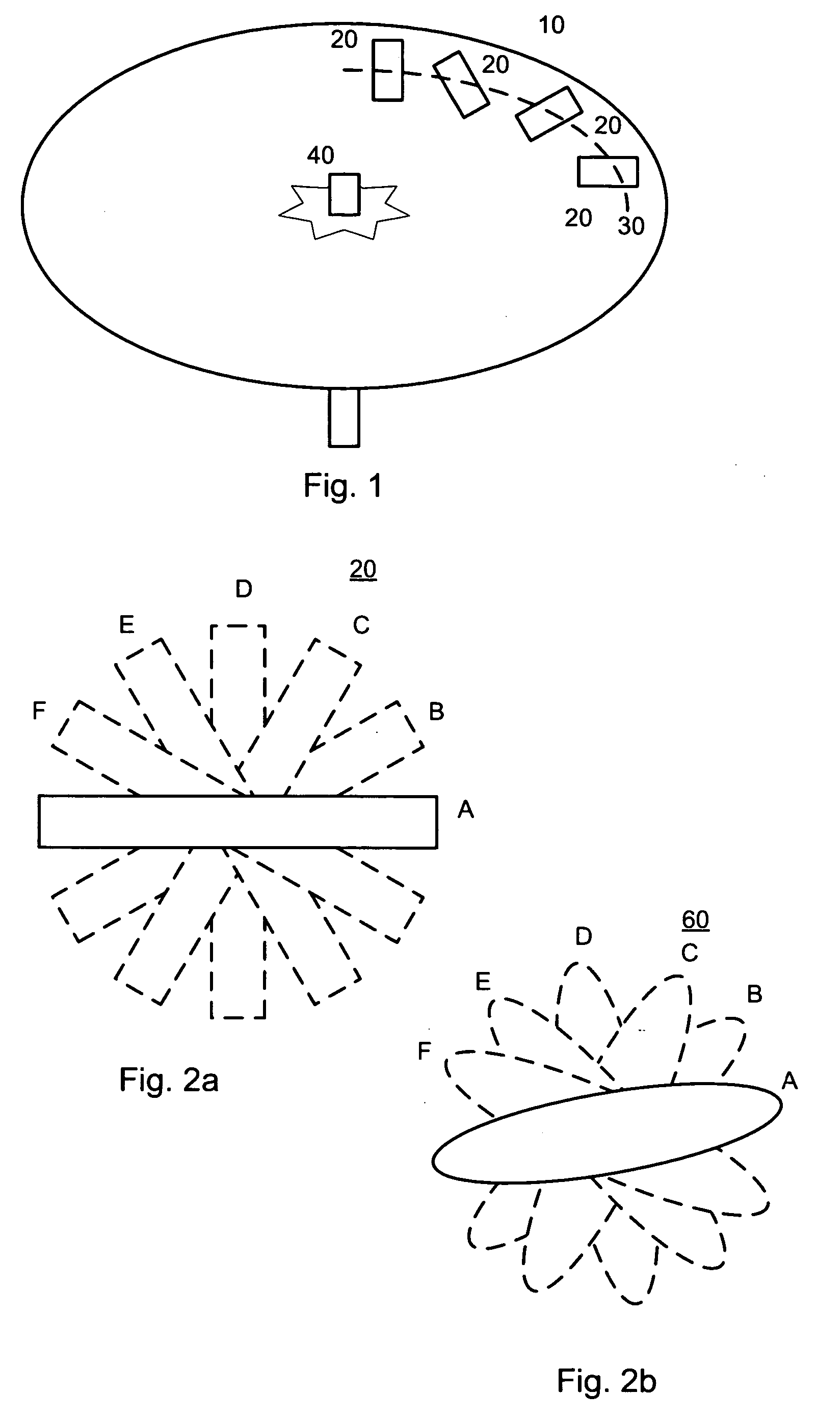
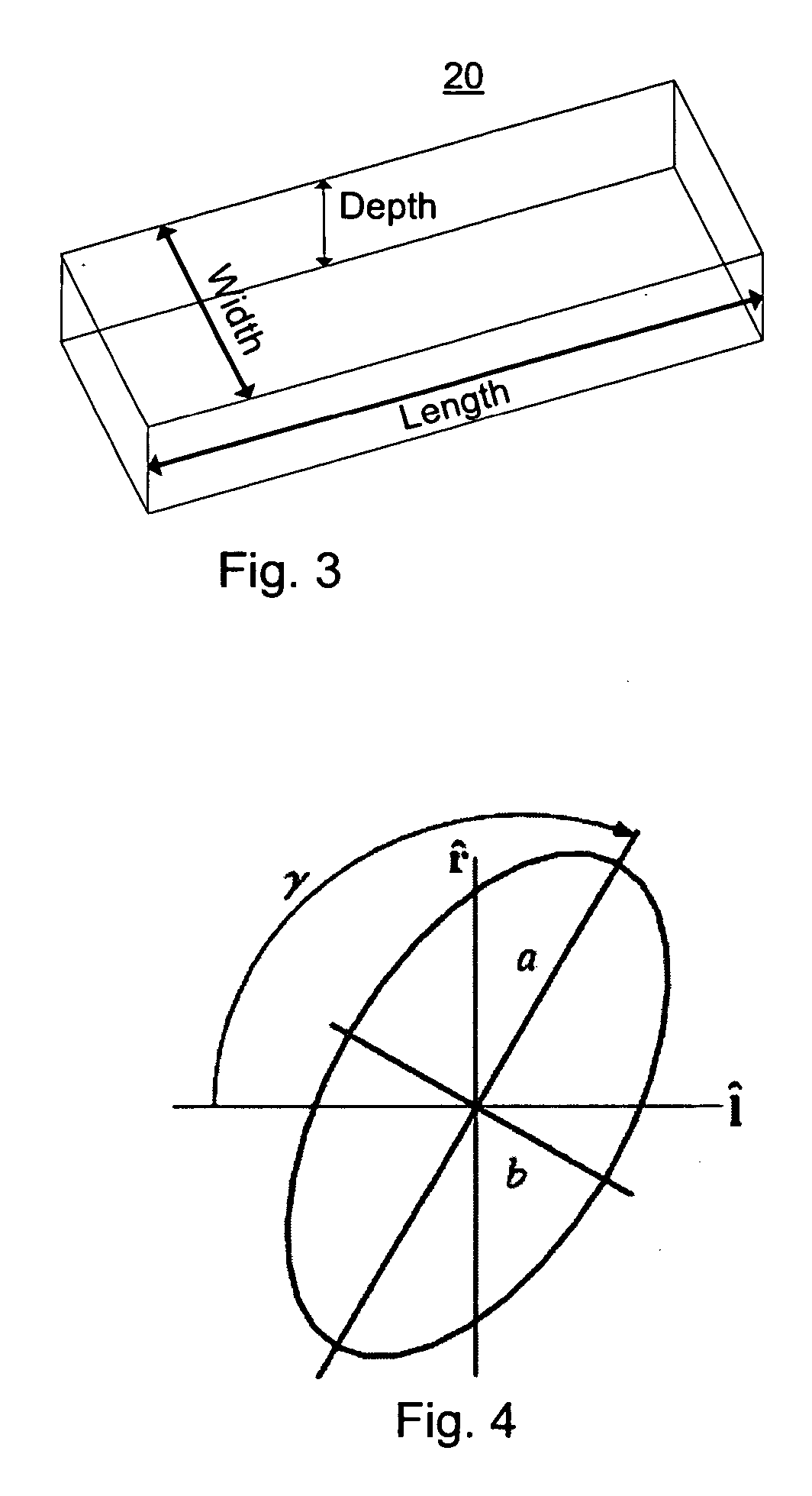
[0053] The present embodiments enable encoding data in an optical memory by planar orientation of marks, such as pits or bumps. The marks are sized to be of sub-wavelength width, with a length comparable to, or larger than, the wavelength. The operative wavelength is hereinafter denoted by λ. The depth or height of the mark is preferably λ / 4, however other depth or heights may be used without exceeding the scope of the invention. A polarized light source is used to read the mark, typically by one of reflection and transmission. Collected light exhibits an elliptic anisotropy, with the principle axis of the ellipse corresponding to the planar orientation of the mark. The collected light is detected by a plurality of polarization sensitive detectors, the intensity and polarization pattern of the collected light indicating the direction of the axis of the ellipse. Thus, the varying planar orientation of the mark encodes the data.

[0054] The specific relationship between the pit mark or...


PUM

PropertyMeasurementUnit
anglesaaaaaaaaaa
θaaaaaaaaaa
polarization anglesaaaaaaaaaa

Abstract

An optical storage medium designed to be readable with light of a pre-determined wavelength, the optical storage medium comprising: a substrate; and a plurality of optically detectable marks imprinted on the substrate, each of the plurality of optically detectable marks exhibiting: a predetermined length; a width less than the pre-determined wavelength; and one of a plurality of orientations in relation to a common axis, wherein information is stored on the optical storage medium at least partially as a function of the one of a plurality of orientations. Preferably the optically detectably marks alter the polarization characteristics of an incident polarized light of the pre-determined wavelength, the altered polarization characteristics being detectable by at least one detector.

Description

CROSS-REFERENCE TO RELATED APPLICATIONS [0001] This application claims priority from provisional patent application Ser. No. 60 / 598,840 filed Aug. 5, 2004 entitled “Method and Apparatus for Optical Data Storage” the entire contents of which are incorporated herein by reference; provisional patent application Ser. No. 60 / 650,964 filed Feb. 9, 2005 entitled “Methods for Encoding and Detection of Information in Multi-state Pit Marks” the entire contents of which are incorporated herein by reference; and provisional patent application Ser. No. 60 / 674,300 filed Apr. 25, 2005 entitled “Methods and System for Encoding and Optical Detection of Information” the entire contents of which are incorporated herein by reference.BACKGROUND OF THE INVENTION [0002] The invention relates generally to the field of optical data storage and in particular to a means for increased data storage based on pit orientation. [0003] The increasing need for data storage has been a consistent driver for expanding t...

Claims


Application Information

Patent Timeline
Patent Type & Authority Applications(United States)
IPC IPC(8): G11B7/00
CPCG11B7/005G11B2007/0013G11B7/24088G11B7/131
Inventor ZACHAR, ORONMANSURIPUR, MASUD
Owner POLARIZONICS CORP
Why Eureka
Try Eureka