Angled Adsorbent Filter Media Design In Tangential Flow Applications

a filter media and tangential flow technology, applied in the direction of lighting and heating apparatus, heating types, separation processes, etc., can solve the problems of affecting the quality of air in many urban areas, affecting the occupants and operations of buildings, and causing nausea and headaches, etc., to achieve the effect of low pressure drop

Active Publication Date: 2019-01-24
ENVIRONMENTAL MANAGEMENT CONFEDERATION
View PDF1 Cites 1 Cited by
  • Summary
  • Abstract
  • Description
  • Claims
  • Application Information

AI Technical Summary

Benefits of technology

[0032]A media design for modular use in an air cleaning or HVAC system to removes gas phase contaminants. The design allows for a control of gas contaminant removal using variable media length, path length, and contact time to ensure a contained MTZ length and low pressure drop. In one embodiment, the

Problems solved by technology

Gas phase contaminants come from a myriad of indoor and outdoor sources and can have a variety of deleterious effects on the occupants and operations in a building.
Exposure to VOCs may cause symptoms from nausea and headaches to liver or lung damage.
Many urban areas do not have air of sufficient quality and it must be cleaned before it can be used.
Gas phase contaminant removal systems can be large, expensive, difficult to install and costly to maintain.
An MTZ length determines the efficiency and lifetime of the media rather than capacity but is not typically used in industry as it is difficult to measure and can be time consuming and difficult to measure.
Many HVAC systems do not have powerful enough fans for additional pressure drop, limiting the application of air cleaning in existing systems.
Even when fans are large enough and/or the need for air cleaning was considered in the original design, high pressure drop may increase energy and operational costs.
Further, carbon pellet systems shed carbon dust and downstream particle filters are necessary, resulting in additional pressure drop as well as additional space requirements.
Pellet trays provide random airflow channels and the moving air will seek out the shortest path therethrough, rendering some portions of the pellet tray unused or under-used.
Over time pellets are subject to d

Method used


Image

  • Angled Adsorbent Filter Media Design In Tangential Flow Applications
  • Angled Adsorbent Filter Media Design In Tangential Flow Applications
  • Angled Adsorbent Filter Media Design In Tangential Flow Applications

Examples


Embodiment Construction

[0047]Filter Media Module

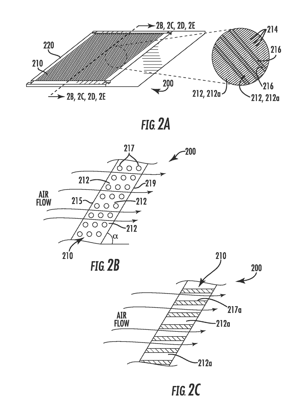
[0048]As shown in FIGS. 2A-2E, 3A and 3B, 4A-4D, 5A, 5B, an air filter module 200, 400, may be removably placed within in an air filter system 300 (generally called “air filter” herein) that itself may be removably placed within an air duct or passage 90 to filter air passing therethrough. In order to maximize the filter media 214, 414 exposure to the air flow to be filtered, and to minimize pressure drop, a filter module 200, 400 may be angled to the air flow, with it being appreciated that the shortest path for air flow from a front of the filter module (facing the air flow) to the back of the filter module is defined along the line shown as cross sectional line 2B, 2C, 2D, 2E—2B, 2C, 2D, 2E, which contrasts with the longer channel air flow path lengths through the channels as described throughout this application.

[0049]For example, channels 212, 212a, 412, 412a through the filter module 200, 400 may be oriented parallel to the air flow to minimize pressur...


PUM

PropertyMeasurementUnit
Angleaaaaaaaaaa
Lengthaaaaaaaaaa
Angleaaaaaaaaaa

Abstract

A media design for modular use in an air cleaning or HVAC systems to removes gas phase contaminants. The design allows for a control of gas contaminant removal using variable media length, path length, and contact time to ensure a contained MTZ length and low pressure drop. In one embodiment, the design includes a filter module at an angle to an airflow and an air filter mounted within the filter frame. The filter module may include channels therethrough that are oriented at the optimum angle in relation to the airflow to provide the required dwell time and pressure drop for a given application.

Description

BACKGROUND[0001]In recent years the purification of indoor air has become more prevalent due to the health implications for the building occupants. The EPA defines indoor air quality (IAQ) as “the air quality within and around buildings and structures, especially as it relates to the health and comfort of building occupants.” Poor IAQ can be tied to symptoms like headaches, fatigue, trouble concentrating, and irritation of the eyes, nose, throat and lungs. Air quality is also critical for the processes and equipment in buildings. Data centers, for example, have few people but many servers that are sensitive to airborne contaminants. These contaminants may fall into three broad categories: particle, biological, and gas phase. Although gas phase contaminants may be discussed in detail herein, the application of the filter described below is not so limited. Similarly, although the description mentions “air flow” and “air filter,” other fluids may be filtered using the filter discussed ...

Claims


Application Information

Patent Timeline
IPC IPC(8): B01D53/04B01D53/52B01D53/56B01D53/62F24F3/16F24F8/158
CPCB01D53/0407B01D53/523B01D53/56B01D53/62F24F3/161B01D2253/102B01D2253/3425B01D2253/308B01D2253/311B01D2257/302B01D2257/304B01D2257/404B01D2257/504B01D2257/708F24F2003/1625B01D53/0415B01D2258/06Y02C20/40F24F8/158Y02A50/20B01D46/0036B01D46/0002B01D46/521F24F3/167B01D46/56
Inventor WISER, III, FORWOOD C.NASKE, CAITLIN
Owner ENVIRONMENTAL MANAGEMENT CONFEDERATION
Why Eureka
Try Eureka