Media Design for High TPI for Write Fringing Reduction

a write fringing and media design technology, applied in the field of magnetic recording systems, can solve the problems of low magnetic write width, write field loss, and loss of overwrite (ovw) from the head, and achieve the effect of improving dtr media design and reducing the risk of adjacent track erasur

Inactive Publication Date: 2011-04-14
SEAGATE TECH LLC
View PDF30 Cites 1 Cited by
  • Summary
  • Abstract
  • Description
  • Claims
  • Application Information

AI Technical Summary

Benefits of technology

[0010]These and other disadvantages of prior techniques are overcome by the present invention, which is an improved DTR media design for a high track per inch system. The DTR media of the present invention includes ferromagnetic islands that are disposed in the air gap grooves between tracks. The ferromagnetic islands act to conduct the write fringing magnetic flux into the soft underlayer of the media to thereby reduce the risk of adjacent track erasure.
[0011]More specifically, in a first embodiment of the invention, a ferromagnetic island is located within each groove between tracks in the media. The island is flush or slightly recessed from the top recording layer of a magnetic recording disk. The bottom of the islands are located adjacent to the bottom of the recording layer. The magnetic properties of the ferromagnetic islands are selected to conduct the fringe field flux directly downwardly into the soft underlayer of the media. This technique minimizes the loss of on-track write field and minimizes the strength of erase field in adjacent tracks.

Problems solved by technology

However, this results in a low magnetic write width (MWW), which can in turn result in write field loss, and thus loss of an overwrite (OVW) from the head.
Furthermore, in a standard head media design, the head field in the off-track direction is found to decay slowly.
This slow decay is disadvantageous because it adds to further adjacent track erasure as the fringe field decays.
It has been challenging to address this problem because the size of the write head, the amount of the fringe field, the fly height of the head, and the interlayer thicknesses in the media are parameters that are involved in the phenomenon, however, such parameters are essentially set and cannot be readily changed.
However, the side shield on the pole tip can reduce the field strength of the write field, which is undesirable.
Moreover, it is also not desirable to require an additional component to be added to the write pole.

Method used


Image

  • Media Design for High TPI for Write Fringing Reduction
  • Media Design for High TPI for Write Fringing Reduction
  • Media Design for High TPI for Write Fringing Reduction

Examples


Embodiment Construction

a method of manufacturing the media in accordance with the present invention;

[0020]FIG. 6 is a schematic illustration of the pre-manufacture layering, which results in improved media of the present invention;

[0021]FIG. 7 illustrates the patterning after the application of the nano-imprint mask used in the second step of the method of manufacture of the present invention;

[0022]FIG. 8 is a schematic illustration of the ion milling step after undercutting the PMMA mask by dissolving part of a B2O3 layer;

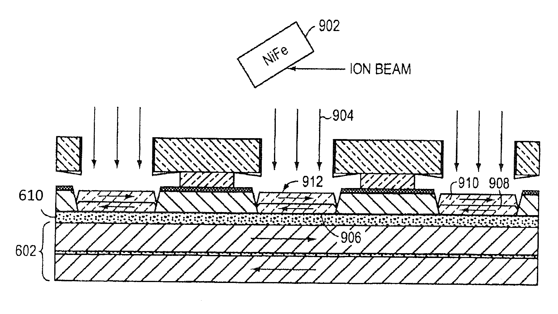
[0023]FIG. 9 is an illustration of the deposition of the soft magnetic material forming a layer of the island in accordance with the present invention; and

[0024]FIG. 10 illustrates the deposition of the final carbon overcoat after mask lift-off, and cleaning steps.

DETAILED DESCRIPTION

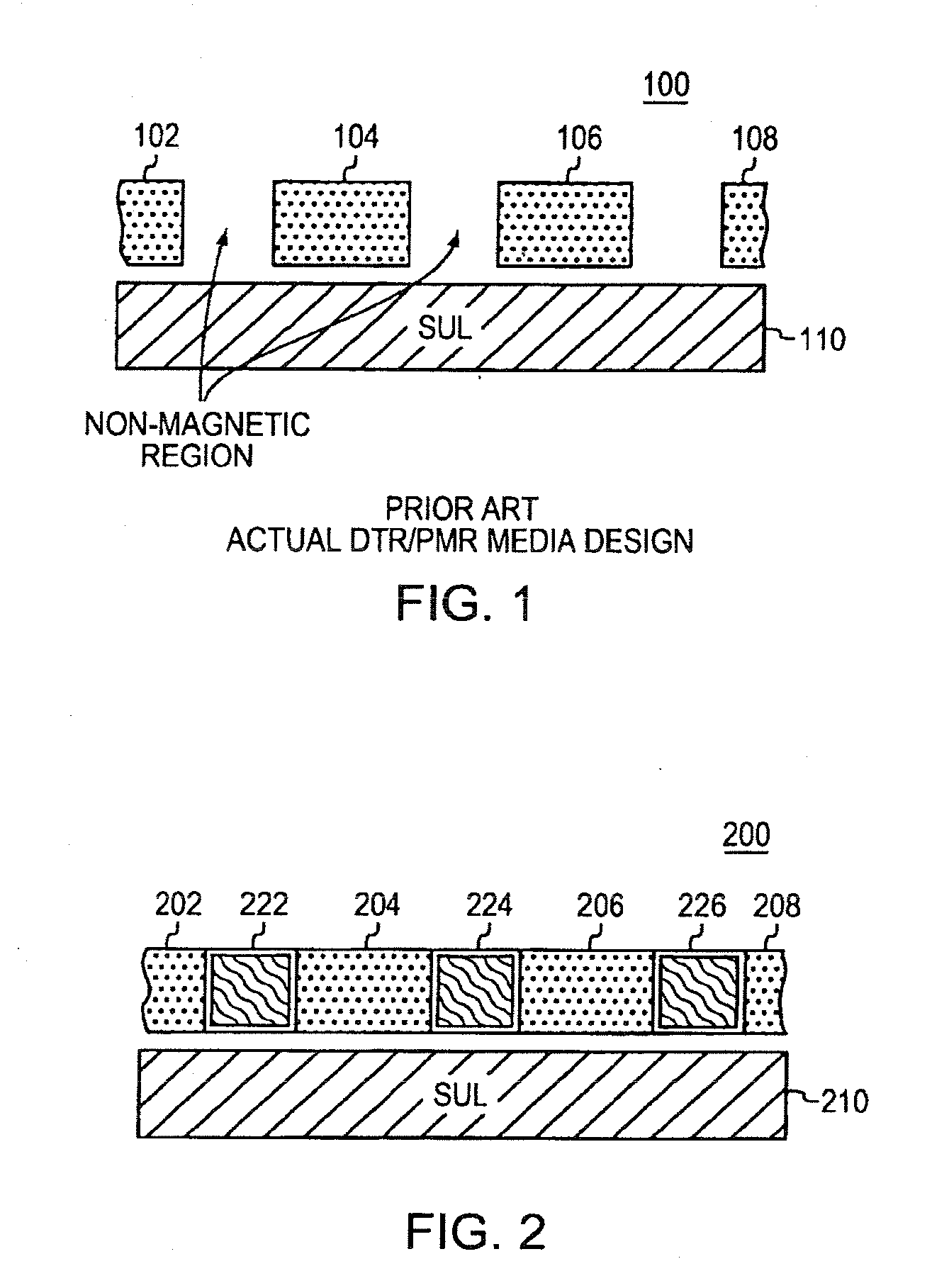
[0025]FIG. 1 illustrates a cross section of a prior art DTR disk media 100. The disk media 100 contains discrete tracks 102 through 108 which comprise the recording layer of the disk media. The discrete tra...


PUM

PropertyMeasurementUnit
thicknessaaaaaaaaaa
widthaaaaaaaaaa
heightaaaaaaaaaa

Abstract

A recording media design having discrete track recording structure where the trenches between tracks are filled with a soft magnetic material is provided. The soft magnetic material provides a low magnetic impedance path to the soft underlayer such that fringe fields from the write head are conducted to the soft underlayer without having a negative effect such as adjacent track erasure. A method of manufacturing the media includes a nano-imprint step and ion milling out the data layer to create the trenches. A B2O3 material allows the data layer to be ion milled out without redeposition bridging the B2O3 layer thus preventing lift off of the mask. The trenches are then filled by ion deposition with the layers of ferromagnetic material separated by an anti-ferromagnetic coupling that causes the flux to be conducted to the soft underlayer and remnant flux to rotate within the island and not into adjacent tracks.

Description

CROSS REFERENCE TO RELATED APPLICATIONS[0001]This application is a continuation of U.S. patent application Ser. No. 11 / 592,507 filed on Nov. 3, 2006, which claims the benefit of U.S. Provisional Patent Application Ser. No. 60 / 733,247, filed Nov. 3, 2005, which are incorporated herein by reference in their entireties.BACKGROUND[0002]1. Field of the Invention[0003]The present invention is related to magnetic recording systems, and in particular, to write fringing reduction in discrete track recording.[0004]2. Background Information[0005]Recently, the trend in magnetic recording is to employ perpendicular magnetic recording (PMR) techniques. In perpendicular magnetic recording, the magnetic domains are aligned perpendicularly to the surface of the disk platter. This allows bits to be placed closer together on the platter, thus increasing storage density to an amount greater than that which has been achieved in conventional longitudinal recording.[0006]A further way to increase bit dens...

Claims


Application Information

Patent Timeline
Patent Type & Authority Applications(United States)
IPC IPC(8): G11B5/74G11B5/82G11B5/62
CPCG11B5/82G11B5/667G11B5/855
Inventor BENAKLI, MOURADMALLARY, MICHAEL
Owner SEAGATE TECH LLC
Why Eureka
Try Eureka