Potentiating support with side struts spanning hinge joint
- Summary
- Abstract
- Description
- Claims
- Application Information
AI Technical Summary
Benefits of technology
Problems solved by technology
Method used
Image
Examples
first embodiment
a Support
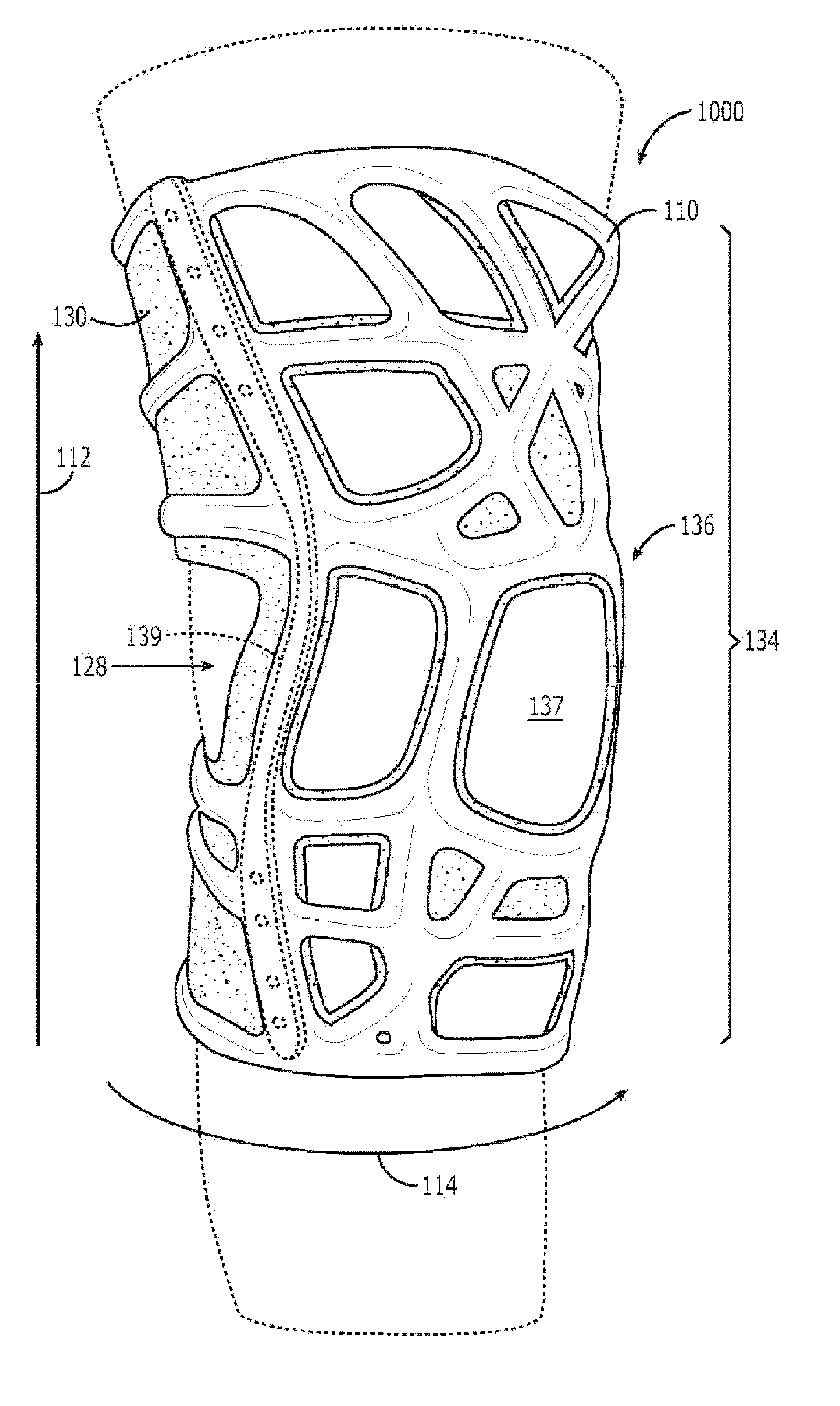
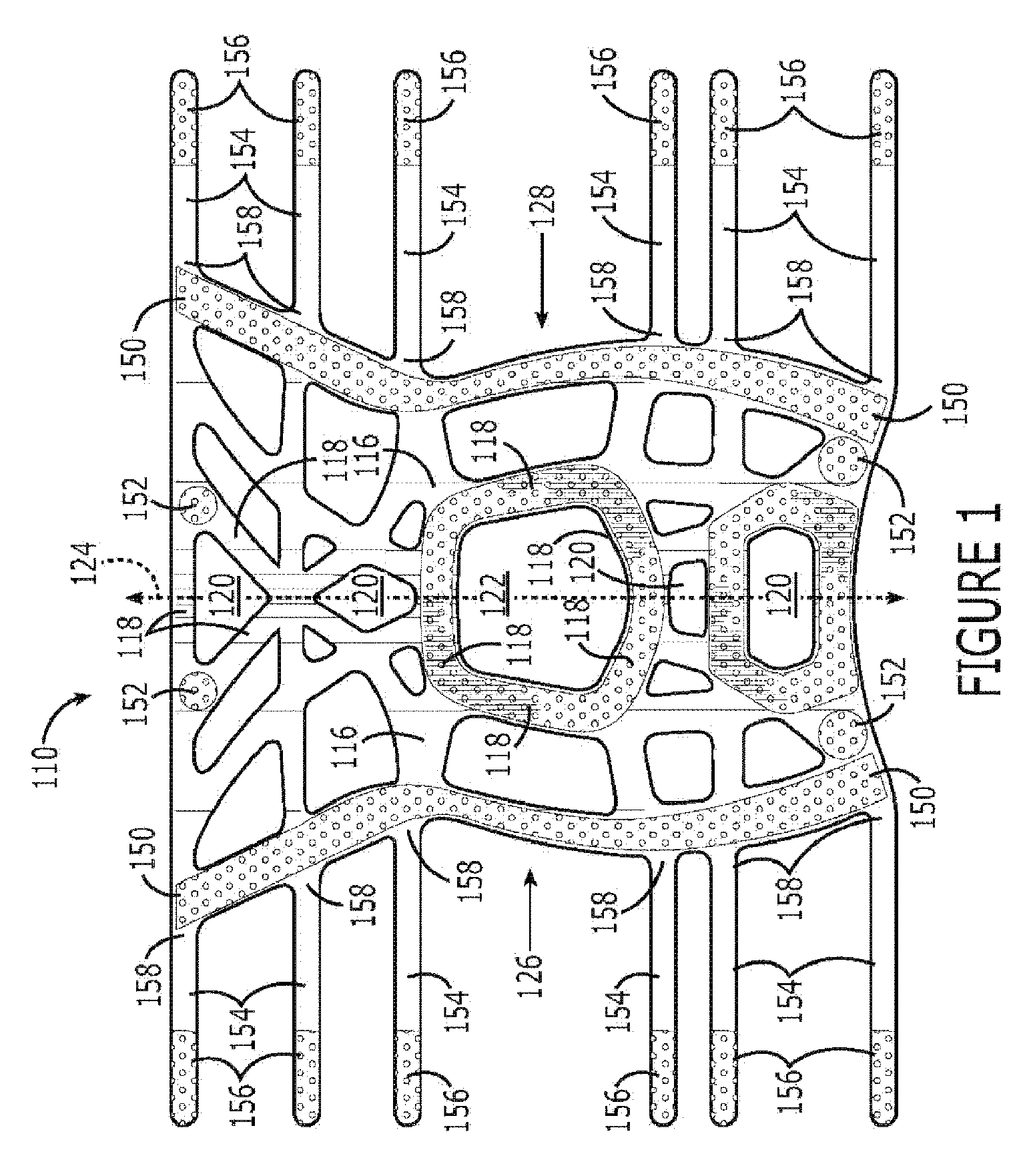
[0122] With regard to the first embodiment of a support for an area of a body, a flexible and elastically stretchable framework 110 thereof is shown in FIG. 1. The framework 110 comprises generally linear segments or members 118 interconnected to define a plurality of permanent openings 120 that extend completely through the framework. Furthermore, some of these openings 120 are completely bounded by the interconnected members 118, and the interconnected members 118 defining such an opening constitute a portion of the framework 110 that is stretchable and recoverable about the entire boundary of the opening with the framework 110. Moreover, the openings 120 are permanent and exist regardless of whether the framework 110 actually is disposed in abutment with the body due to the permanent interconnection of the members 118 defining the openings 120. The framework 110 preferably is formed from an elastomeric material in a conventional molding process and, in this particular em...
second embodiment
a Support
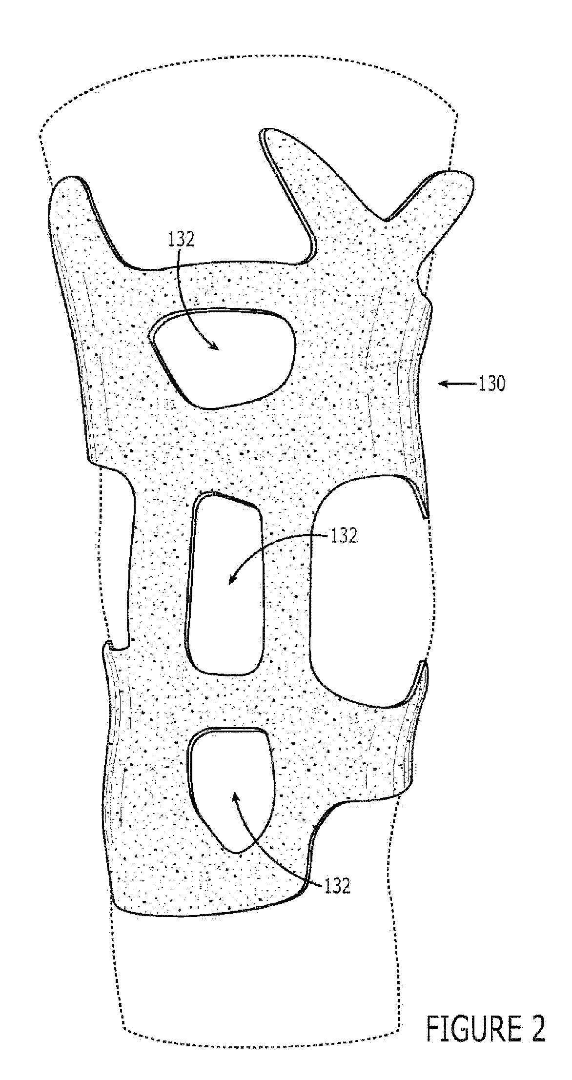
[0135] With regard to the second embodiment 2000 of a support for an area of a body, the second embodiment 2000 includes a framework that is the same as the framework 110 of the first embodiment 1000. The second embodiment 2000 further is considered to include, as part thereof, sleeve 168 (FIGS. 7-8) that is generally the same as sleeve 130 of FIGS. 2-3, except that the sleeve 168 is continuous and does not define openings therein that would register with corresponding openings of the framework 110. As shown in FIG. 7, sleeve 168 includes fasteners covering most of the entire outer surface of the sleeve. Alternatively, as shown in FIG. 8, the sleeve 168 includes certain discrete areas 172 that comprise loop fasteners for receiving the hook fasteners 156 of fastening straps 154 (FIG. 1) and, thus, does not include loop fasteners covering most of the entire outer surface of the sleeve as shown in FIG. 7. FIG. 9 illustrates the second embodiment 2000 including the framework 11...
third embodiment
a Support
[0136] The third embodiment 3000 of a support is shown in FIGS. 10-17 and is the same as the first embodiment 1000 except for the following noted differences.
[0137] First, the embodiment 3000 includes a liner 198 (FIG. 16) that is attached directly to the framework 182 such as, for example, by plasticized welding, elastomeric welding, adhesive attachment, or by sewing. The support further includes two bands 199a,199b (FIG. 16) extending between and directly attached to the two opposite sides of the framework 182.
[0138] Second, the fastening mechanism includes four fastening components, each of which comprises a claw member 196 that is removable from (FIG. 10) and attachable to (FIG. 16) the framework 182. As shown in FIG. 10, each claw member 196 includes a number of fastening belts 200 joined by a fastening pad 202. First faces 204 of the claw members 196 have adjustment-fasteners 206 attached to the fastening belts 200 as shown in FIG. 10. The adjustment-fasteners 206 a...
PUM
 Abstract
Description
Claims
Application Information
 - R&D
- Intellectual Property
- Life Sciences
- Materials
- Tech Scout
- Unparalleled Data Quality
- Higher Quality Content
- 60% Fewer Hallucinations
Browse by: Latest US Patents, China's latest patents, Technical Efficacy Thesaurus, Application Domain, Technology Topic, Popular Technical Reports.
© 2025 PatSnap. All rights reserved.Legal|Privacy policy|Modern Slavery Act Transparency Statement|Sitemap|About US| Contact US: help@patsnap.com


